9-74
“Confidential, Do Not Duplicate without written authorization from NEC.”
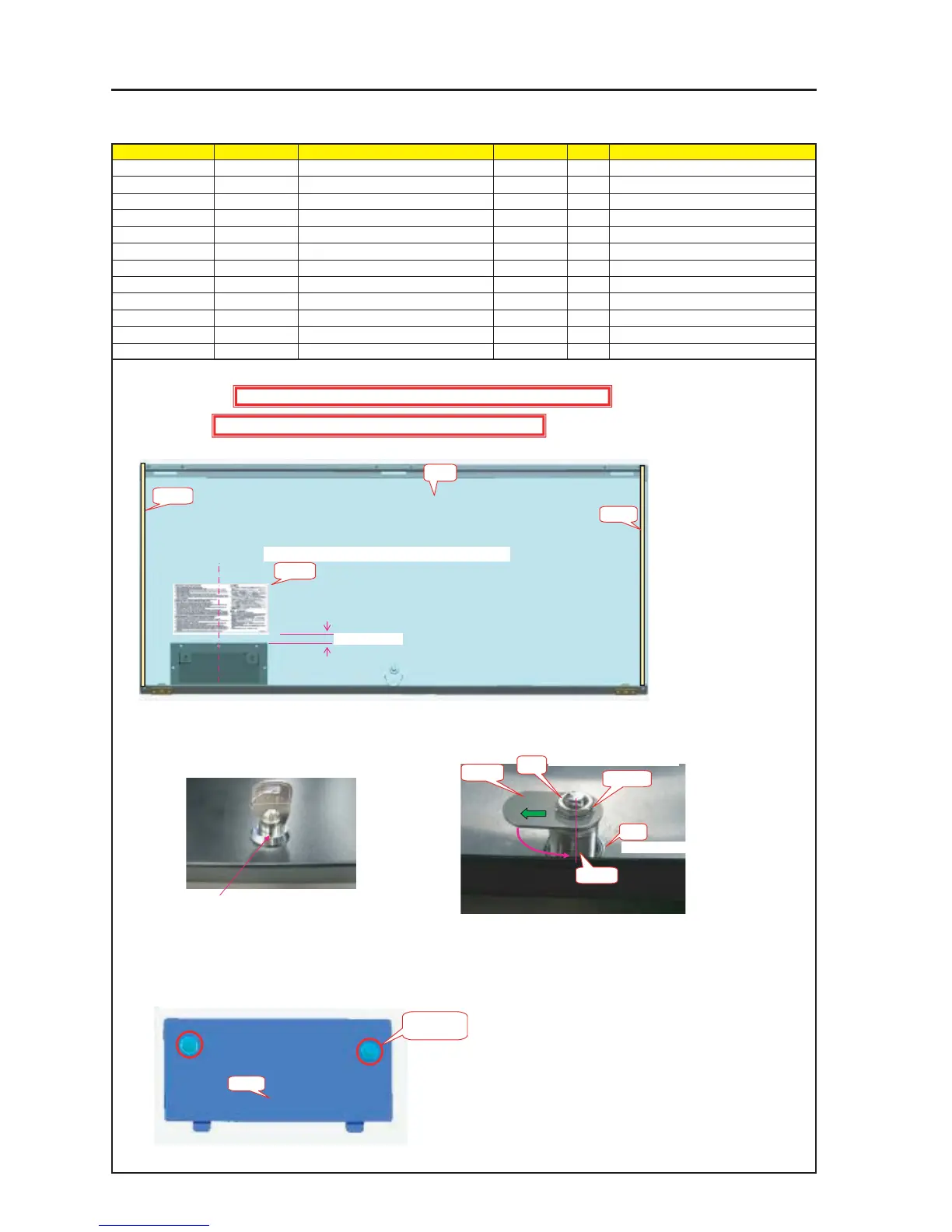
ASSEMBLY DIAGRAM
Diagram symbol Circuit symbol Part name Part code Q’ty Remarks
PRT1 REAR PANEL A ASSY 24PS5311 1
PRT2 KEY(TL-96N-1) 24C09131 1
PRT3 CAM(LOCK)TI 24H61071 1
PRT4 CAUTION LABEL(LAMP) 24L62591 1
PRT5 GASKET(STG1-5) 24C09311 2 315mm
PRT6 COVER(REAR PANEL) 24P05481 1
PRT7 SPECIAL SCREW(M4*18) 24N08431 2 Torque check
PRT8 PIWA*4*3GF 24V00661 2
Rear Panel T Sassy
1 Cut the Gasket (STG1-5) to a piece of 315mm and stick it to the Rear Panel A Assy.
PRT1
PRT5
PRT5
PRT2
Nut2
PRT6
Caution : External parts shall be handled carefully so that they are not damaged.
Caution : EMI (Electromagnetic Interference: Radio interference noise)
Stick it to the front side of the REAR PANEL A ASSY
PRT4
PRT7 X 2P
PRT8 X 2P
PRT3
Nut1
10mm~20mm
Caution: Confirm that the Key can be pulled out after Key locking.
If it cannot be pulled out, change the direction of washer attached to the key and reinstall it.
Washer
In the state that the key is inserted (unlocked),
the notch section shall be faced toward outside.
(Panel end side)
Mount the CAM (LOCK) TI on the left side as seen from the panel end.
Caution: When the key is pulled out, the CAM (LOCK) TI is faced to the
bottom side. (Located on the Panel end side)
Tightening torque : 32±2kgf•cm
Tightening torque : 100±5kgf•cm
2 Remove Nut 2 of the Key (TL-96N-1) and pass the Key (TL-96N-1) through the hole of the Rear Panel A Assy.
Then, tighten the key with Nut 2.
Remove Nut 1 and washer from the tip of the Key (TL-96N-1) and mount the cam (LOCK) TI.
Then, tighten the cam with the same Nut 1 and Washer.
3 Mount the Special Screw (M4*18) and the PIWA*4*3GF on the Cover (Rear Panel).