User Manual
Page 34
1. In Installation > Analog Input:
a. Define a sensor as EC.
b. Define a sensor as EC drain.
2. In Installation > Digital Input define which digital input is the drain meter.
Note: The drainage must be defined correctly! You can check the drainage meter status using Hot Key 9.
3. In Configuration > Valve Configuration define which valve number corresponds to which drainage meter.
4. In Configuration > Dosing Channel Configuration set React to EC.
5. In Configuration > Dosing Configuration > EC Control to Yes.
6. In Configuration > Drainage Configuration, define the drainage meter’s Ratio Liter/Pulse.
7. In Program > Irrigation, select EC Drain/EC.
a. Define the EC Drain percentage set points.
b. Define the EC percentage set points.
8. Set ACTIVE/SOURCE to Yes.
9. Press Menu and confirm changes.
10. In Program > Dosing Program set the Target EC.
Note: You can disable this function by disabling EC Control (Configuration > Dosing Configuration).
Example: A user wants to maintain an EC level of 1.5. To this end, he measures the drainage EC. When the drainage
EC falls below 1.5, he increases the EC input. As it rises above 1.5 ms/cm, he decreases the input.
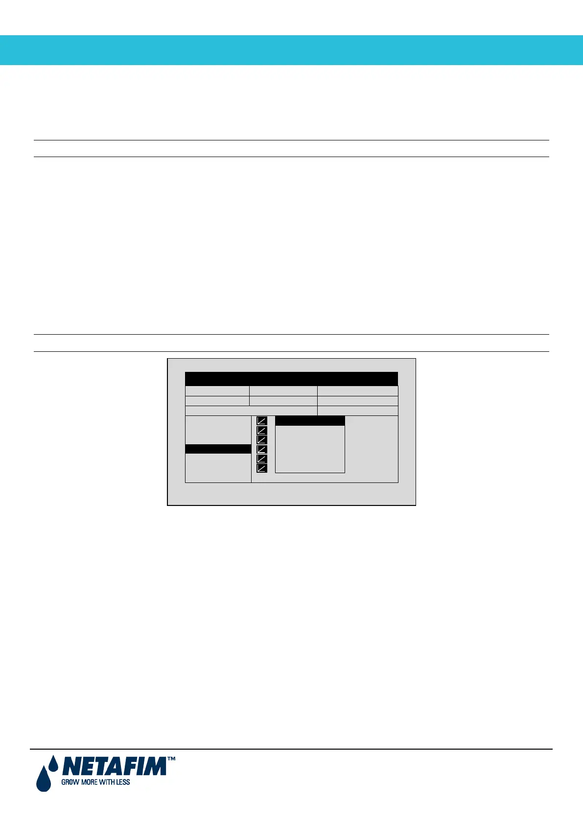
DATE: 2 –Feb-12 TIME 12:52-08
IRRIGATION PROGRAM
INFLUENCE TABLE ACTIVE/SOURCE
Drain/RadS
mS/cm (%)
VPD/EC
3 -20
Screen 2 of 2 – In order to view the