User Manual
Page 50
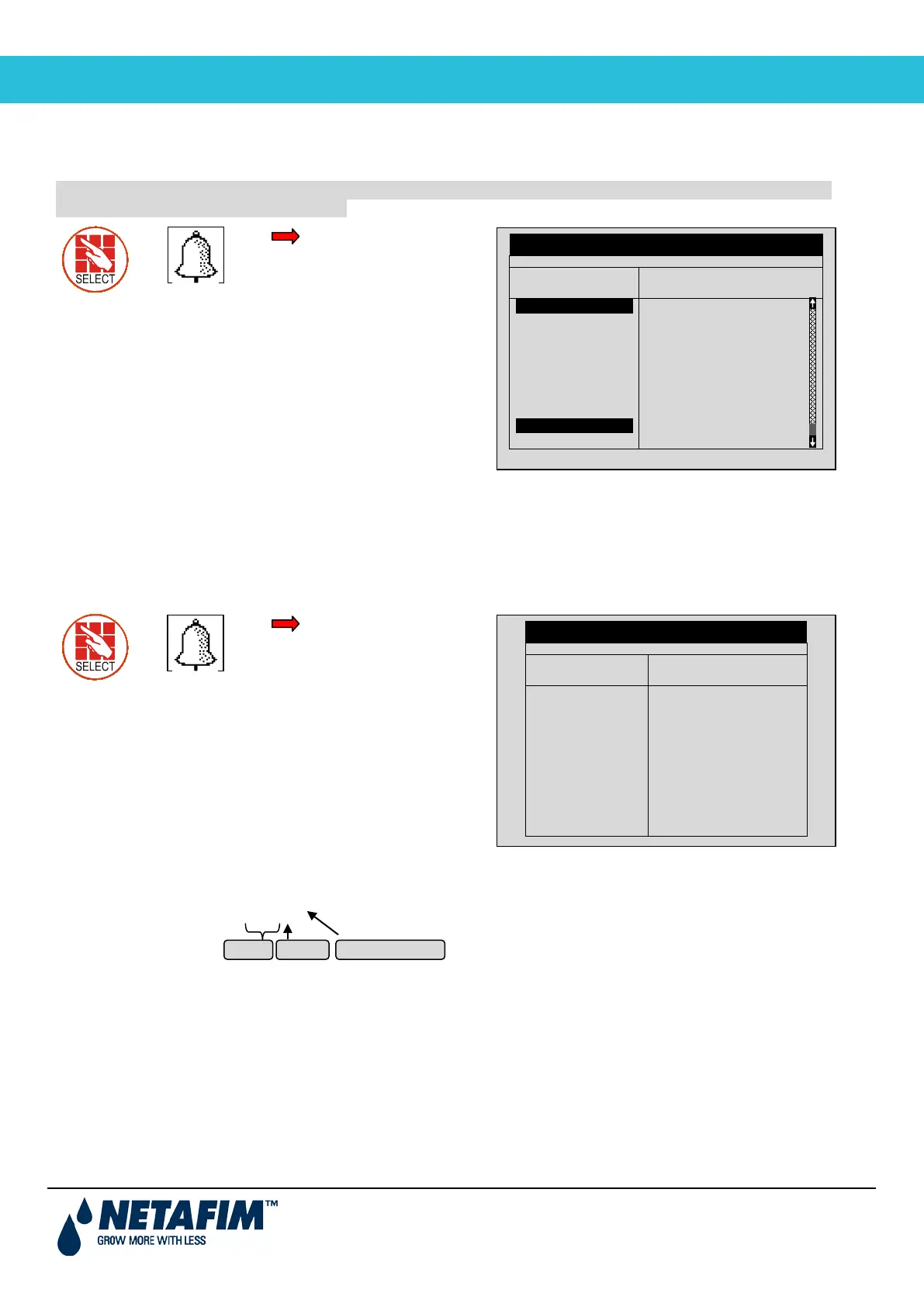
4.7 34BRadio System Alarm Definition
Use this function to define Radio Systems alarm activity and notification.
IMPORTANT: For the Radio System to work properly, you MUST define in the 6.2 SYSTEM SETUP menu –
Remote Unit type parameter SN/RF Net.
Definition
• The ACTIVE column defines if the alarm is used in making a decision regarding the irrigation program (YES /
NO)
• The INFORM column defines if the system notifies the user of the alarm occurrence (YES / NO)
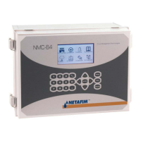
4.8 35BRadio System Alarm View
This screen displays the current alarm status of the Radio System.
View
The S/N column is the unit number. When an Open Circuit or Short Circuit alarm is detected, the system also displays
the card number and the input/output number that is problematic.
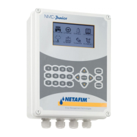
For example: RTU – 0555.3.1
Exiting and re-entering refreshes the alarm status screen.
RADIO SYS. Alarm view
Unit S/N Comm
state
Card
BASE
RTU
RTU
RTU
RTU
RTU
RTU
RTU
RTU
0117
0236
0115.3.4
0513.4.1
0198
0555.3.1
----
----
----
FAIL
OK
-
-
-
-
-
-
-
-
-
OK
FAIL
WARN
LOW
-
-
-
-
3.1
RADIO SYS. ALARM DEFINITION
Alarm Type
mm:ss
Vbatt failure
Vbatt low
Vbatt warn
Cap failure
Card failure
I/O Open
I/O Shor
HOST
Over current
00:00
00:00
00:00
00:00
00:00
00:00
00:00
00:00
YES
NO
NO
NO
NO
NO
NO
NO
YES
YES
YES
YES
YES
YES
YES
YES
UNIT # CARD # INPUT/OUTPUT#