Page 13 of 121
CHAPTER 2: PHYSICAL
DESCRIPTION
This chapter describes the hardware features of the NETGEAR Model FSM726S and FSM750S Managed Stackable Switch. Topics include:
Front and back panels
10/100 Mbps auto-sensing RJ-45 ports
Gigabit Ethernet Ports (RJ-45 and GBIC module bay)
LED descriptions
Console port
Stacking ports
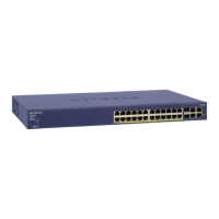
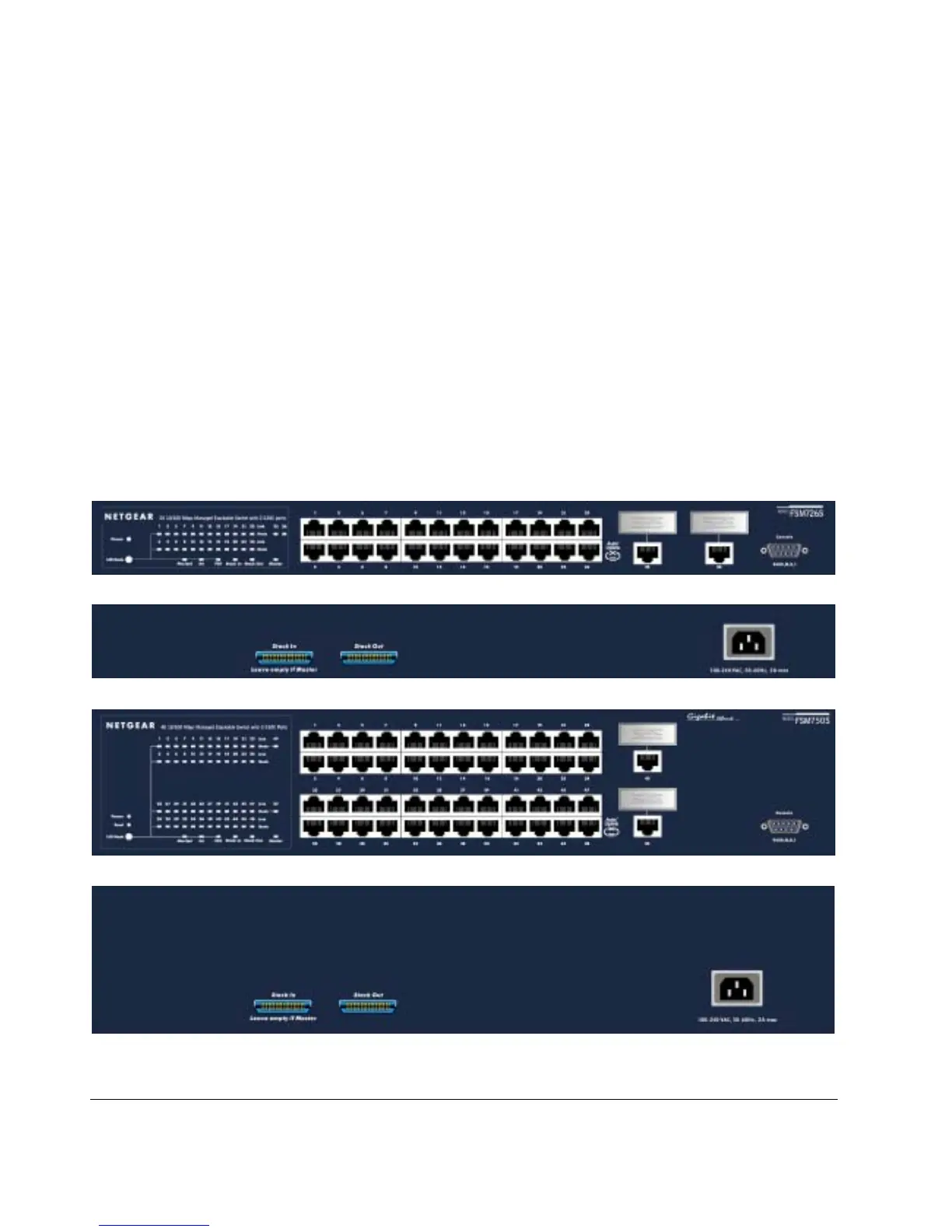
Front Panels
Figures 2-1 and 2-2 show the key components on the front and back panels of the NETGEAR Model FSM726S and FSM750S Managed Stackable
Switch
The front panel contains LEDs, RJ-45 jacks, GBIC module bays, and a console port. The back panel has two stacking ports and a standard AC
power receptacle for accommodating the supplied power cord.
Figure 2-1: Front Panel of the FSM726S Managed Stackable Switch
Figure 2-2: Back Panel of the FSM726S Managed Stackable Switch
Figure 2-3: Front Panel of the FSM750S Managed Stackable Switch
Figure 2-4: Back Panel of the FSM750S Managed Stackable Switch
 Loading...