User Manual MX Series Voice Gateway
16 New Rock Technologies, Inc.
Four interface slots; each can contain one 24-port interface card.
Note: The interface card is hot swappable, but you should reboot the device after the
replacement of the interface card!
Numbering definition of system interface slots: on the low-left side of chassis is #1 slot (marked with No.1
to 24), on the low-right side of chassis is #2 slot (marked with No.25 to 48), on the up-left side of chassis
is #3 slot (marked with No.49 to 72), and on the up-right side of chassis is #4 slot (marked with No.73 to
96).
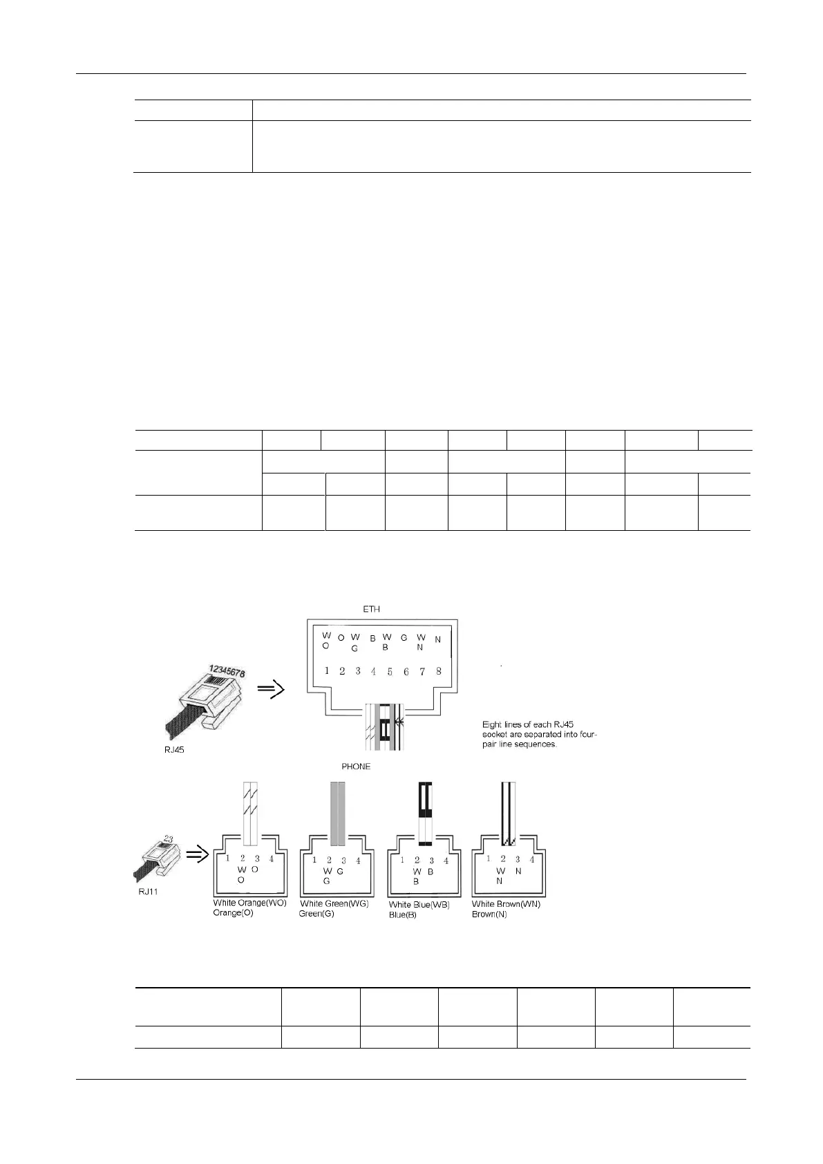
Each RJ45 socket has 8 pins leading out 4 pairs of analog telephone or trunk lines in agreement with the
pair specifications for Ethernet interfaces, whose corresponding relations can be seen in the table below.
CAT-5 cables are used to connect the interface card and distribution panel in equipment installation.
Standard RJ11 telephone lines can be used to plug in a RJ45 socket. The telephone/trunk lines are connected
to the 3
rd
pair of pins for simple call test.
Table 1-27 Pin Specifications for MX120G RJ45 Socket Port
Figure 1-16 Schematic Diagram of MX120G Subscriber Line Connection
Table 1-28 Corresponding Relation Between MX120G RJ45 Socket and Line Number