Safety
information
Product
information
Mechanical
installation
Electrical
installation
Getting
started
User Menu A
Commissioning
Advanced
Parameters
Diagnostics Optimization CT MODBUS RTU Technical Data
174 Installation and System Design Guide
Issue Number: 1
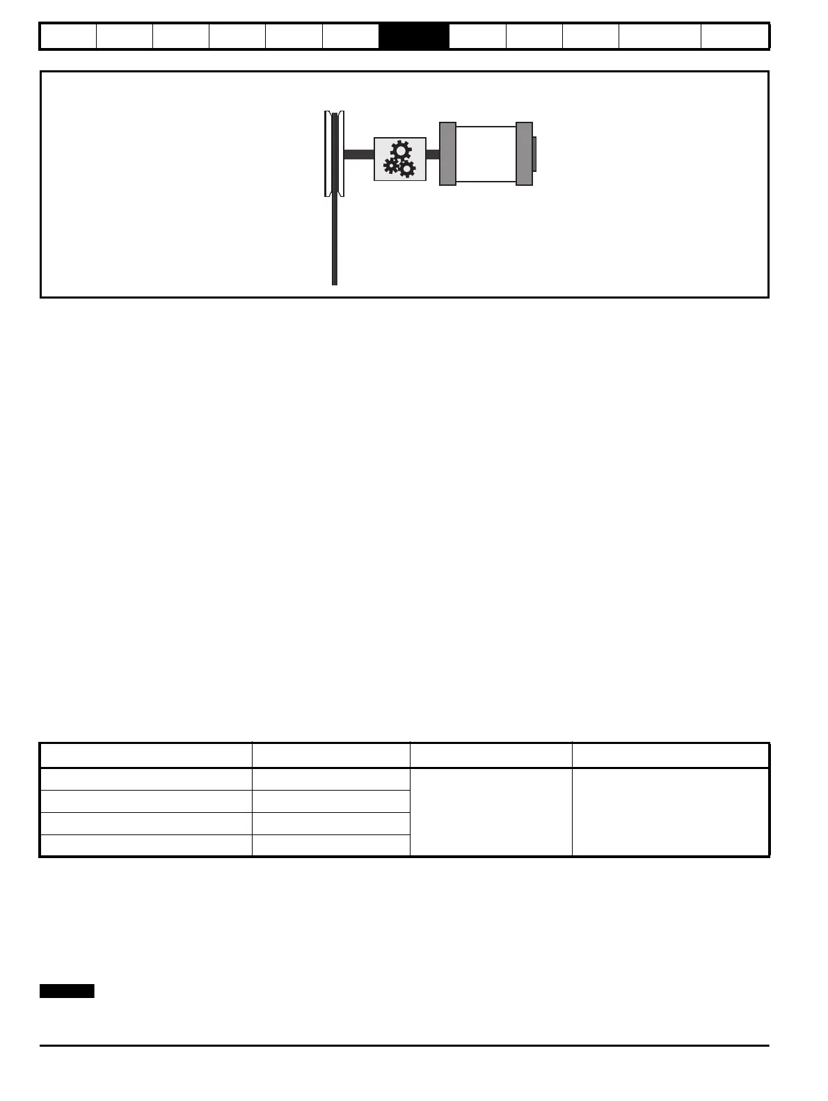
Figure 7-3 Elevator mechanical data
7.6 Creep to floor profile
The default operating mode for the E300 Elevator drive is RFC-S mode (closed loop servo) for permanent magnet synchronous servo motors in
gearless Elevator systems with Creep to floor positioning. Positioning with Creep to floor is a commonly used operating mode.
For all sections of the profile shown below, there are independent parameters available for the Start optimization, Jerks, Acceleration, Deceleration
and Creep to floor which allow the ride comfort of the Elevator to be optimized.
For Creep to floor operation, the operating speed is selected according to the Elevator landing distance. The E300 Elevator drive by default uses
digital pre set speed selections set-up in V1 Creep Speed Reference (G01) to V4 Speed Reference (G04) as detailed below.
The Creep speed is configured to be V1 Creep Speed Reference (G01) in Creep Speed Selector (G52) the remaining speed selections V2, V3 and
V4 can be configured for any speed e.g Nominal speed, High speed, Low speed.
In addition to controlling the profile, the deceleration distance is also calculated in mm dependent upon the speed selected shown in Reference
Parameter Selected (J09)) and the profile settings. The calculated deceleration distance is displayed in Deceleration Distance Calculated (J43) for
the activated speed.
The measured deceleration distance is displayed after every travel in Deceleration Distance Measured (J44) in mm. The measured Creep speed
distance is also available and shown in Creep Distance Measured (J45).
The real-time demand on the Elevator control system is low with Creep to floor positioning with a typical cycle time of the Elevator controller of 5 to
20 ms whilst operating over digital terminal control and the E300 Elevator drive in the region of 8 ms the minimal positioning distance with Creep to
floor is calculated as follows:
The maximum Creep speed distance =
Positioning distance [mm] ≥ V
Nominal
[m/s] x 30 ms
The stop accuracy =
Accuracy [mm] ≤ V
Creep speed
[m/s] x 30 ms
The time required for the Creep speed =
Time Creep speed [ms] = positioning distance [mm] / V
Creep speed
[m/s]
Table 7-11 Elevator speeds and distances
The timing diagram in Figure 7-4 Creep to floor profile, Timing diagram on page 175, shows the sequence of operation in the Creep to floor mode as
is also detailed below:
• A start sequence is received at the drive from the Elevator controller by means of selecting both a speed and direction.
• Following selection of both the speed and direction inputs on the drive, the Elevator controller then closes the output motor contactors. On closing
the output motor contactors, the Safe Torque Off (STO) Drive enable is applied to the drive, and if the Fast disable is used this is also applied and
the drive’s output becomes active.
• Once enabled, the symmetrical drive current limit is ramped up and torque is generated along with Start locking becoming active if enabled.
• With the drive holding the motor at zero speed the brake is opened and the profile started.
Following any system fault where a drive trip may occur, and the brake control is carried out by the drive, the brake is automatically closed and the
drive output disabled.
Speed selected Speed setting Distance Measured, calculated distances
V1 Speed Reference (creep speed, G52) G1 Speed Reference
J42 Deceleration distance
J43 Deceleration distance calculated
J44 Deceleration distance measured
J45 Creep distance measured
V2 Speed Reference G2 Speed Reference
V3 Speed Reference G3 Speed Reference
V4 Speed Reference G4 Speed Reference
Elevator
motor
Elevator
gearbox
Elevator
sheave
Elevator
roping
A Nominal elevator
speed (motor) rpm
B Nominal elevator
speed mm/s
C Sheave
diameter
D Roping
E Gear ratio
numerator
F Gear ratio
denominator

 Loading...


