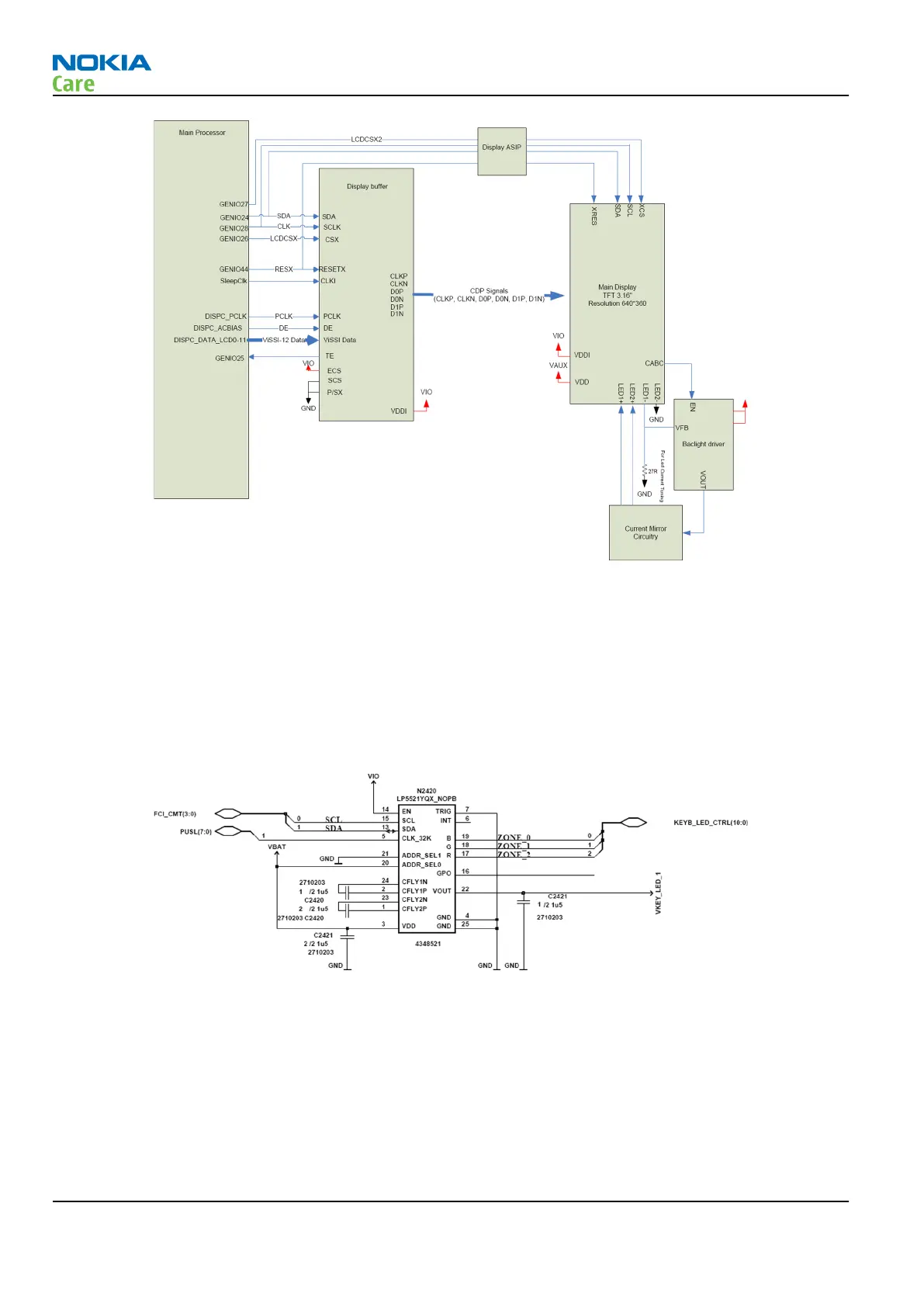
Figure 68 Display block diagram
Backlight and illumination
This device has two backlighting systems; one for the display and one for the HW keys and other illumination
zones.
Backlighting for HW keys
The L5521 LED contoller is used for backlightning the HW keys . There is one LP5521 in the reference HW
making it possible to have up to three LED zones. It can also drive the RGB LED.
Figure 69 Backlight control for HW keys
Display backlights
Display backlights consist of two LED chains, each containing three LEDs in series powered by TPA61061
switching mode power supply. Display backlight brightness is controlled by the CABC signal, and the equality
of the current (and thus the brightness) through the two LED chains is ensured by a current mirror.
RM-356
System Module and User Interface
Page 6 –26 COMPANY CONFIDENTIAL Issue 1
Copyright © 2008 Nokia. All rights reserved.