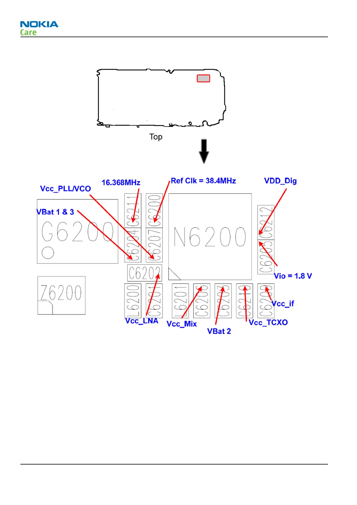
GPS layout and basic test points
Figure 20 GPS layout and basic test points
VBat, ASIC internal LDO voltages, and clocks are available as shown in figure above. In addition to these, the
following GPS signals are available on the test points listed below:
•
GPS_En_Reset (J6201)
•
U2Tx (J6200, activity on this pin indicates the GPS is operating)
GPS RF test points
The GPS antenna test pads are located on the top side as shown in figure "GPS antenna test pads". Checking
for a connection between these two test points will confirm that the antenna is working correctly, as will
performing a radiated CW test.
J6280 = GPS Ant
J6281 = GPS Ant Gnd
RM-356
BB Troubleshooting and Manual Tuning Guide
Page 3 –42 COMPANY CONFIDENTIAL Issue 1
Copyright © 2008 Nokia. All rights reserved.