Terminals, Connectors & Switches
1. Product Description
AFP-100/AFP-100E Instruction PN 51010:C1 02/06/2002
13
Terminals, Connectors & Switches
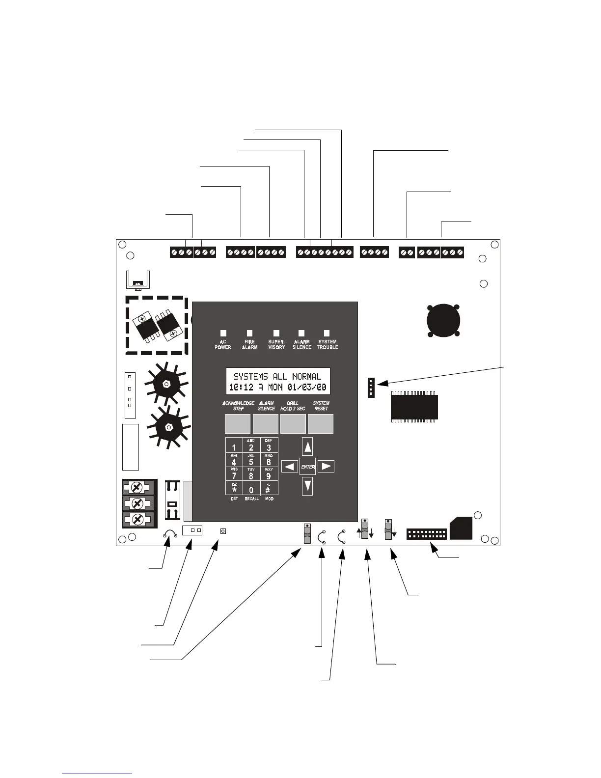
The figure below shows the terminals, connectors and switches that are located on the AFP-100 main
circuit board.
Figure 2 AFP-100 Main Circuit Board
24V UNREG 24V NONRS 24V RST
BELL 2 P OWER
BELL 1 P OWER
SUPV ALARM TROUBLE PC/PRINTER T ERM COMM
GND FAULT
DISABLE
TRANSFORMER 1
TRANSFORMER 2
- +
BATTERY
RS-23 2
PC/PRINTER
RS-485
TERM. MODE
TROUBLE
+ - + - + -
B+ A+ A- B-
B+ A+ A- B-
NO C NO NC C NO NC C
A B B+ A+ B- A-
1 COMM 2
ACS
SHI ELD SLC SLC
OUT+ IN+ OUT- IN-
T
B
4
T
B
2
T
B
1
T
B
3
T
B
7
T
B
5
T
B
6
J16
J6
JP3
JP1
CAUTION
HIGH VOLTAGE
J3
TB8
J19
J17
JP4
SW1
SW3
SW2
CAUTION!
HIGH VOLTAGE
GNDFAULT
TB4 - 24 VDC Power
TB1 - NAC Circuit 1
TB2 - NAC Circuit 2
TB6 - SLC
TB5 - ACS COMM
TB7
TERM COMM
PC/PRINTER
TB3 - Relays
TROUBLE
ALARM
SUPV
TB8 - AC
EARTH
NEUTRAL
HOT
JP1- Battery Charger
Disable
Cut to disable FACP
battery charger when
using external charger
J3 - Battery Connector
JP3 - Ground Fault Disable
Cut to disable Ground Fault
Detection Circuit
SW3 - EIA-232/EIA-485 Selection
Up position selects EIA-232 for PC/Printer
connection.
Down position selects EIA-485 for
Annunciator connection
SW2 - Trouble
Normal position is up for no AC fail
reporting delay.
If using UDACT for Central Station,
SW2 must be down, as shown, to
enable AC Loss Delay reporting.
J6 - Connector for
optional RTM-8F
Module
JP4 - RTM-8F Supervision
Cut jumper to supervise RTM-8F
module when installed
SW1 - Write Protect
Up position is write protect.
Down position, as shown, is
nonwrite protect which
allows panel programming.
Ground Fault LED
J16 -
UDACT
Connector
J17
Xformer 1
High
Voltage
J19
Optional
Xformer 2
High
Voltage
9200bord.cdr
Technical Manuals Online! - http://www.tech-man.com