Installing a RTM-8F Module
2. Installation
AFP-100/AFP-100E Instruction PN 51010:C1 02/06/2002
35
Installing a RTM-8F Module
Caution: Disconnect all sources of power (AC and DC) before installing or removing any modules or
wiring.
Mounting
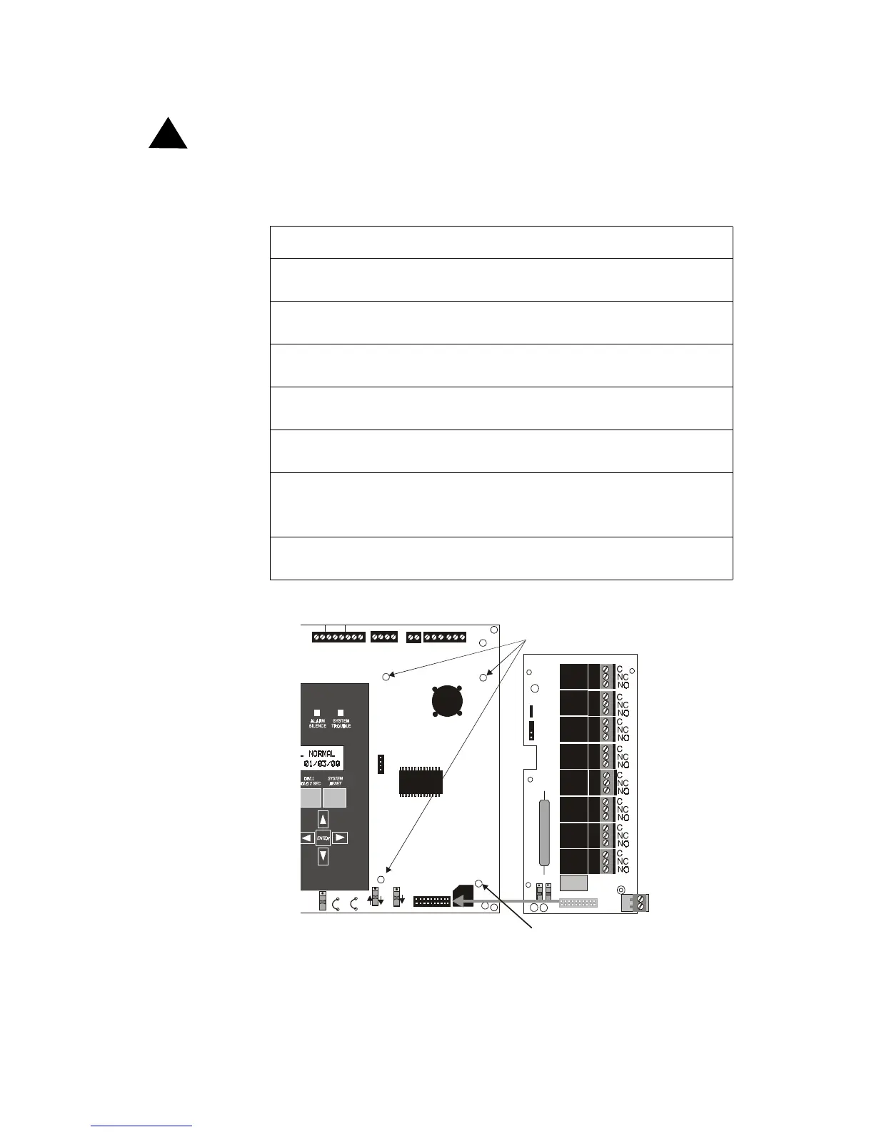
To install an RTM-8F module, follow these steps and refer to the figures below:
Figure 14 RTM-8F Module Installation
Step Action
1 Cut jumper JP4 (to enable module placement supervision) on the Main
Circuit Board.
2 Snap the three 3/4” nylon standoffs (supplied) into the holes located on the
right-side of the Main Circuit Board.
3 Install the 3/4” metal standoff (supplied) into the hole at the lower-right
corner of board. Secure with nut and tighten securely.
4 Carefully align the J1 connector on the RTM-8F module board with the pins
of J6 on the Main Circuit Board.
5 Press firmly on the RTM-8F until it locks in place on the standoffs and the
connector is seated onto the pins.
6 Secure RTM-8F to the Main Circuit Board at the lower-right corner
mounting standoff (metel) using the provided screw. Tighten securely.
Note: This is critical to the RTM-8F transient protection.
7 If required, affix the terminal identification labels (see Figure 15 on page
36).
!
SUP V ALAR M TR OU BLE PC/ PR INTE R T ER M COM M
GND FAULT
DISABLE
RS-232
PC/PRINTER
RS-485
TERM . MODE
TROUBLE
NO C N O NC C NO NC C
A B B+ A+ B- A-
1 COMM 2
ACS SHIE LD SL C SL C
OUT + IN+ OUT- IN-
T
B
3
T
B
7
T
B
5
T
B
6
J16
J6
JP3
JP4
SW1
SW3
SW2
RTM-8F
AFP-100 Main Circuit Board
3/4 inch nylon standoffs
3/4 inch aluminum standoff with nut
(Required for transient protection)
9200RTM8.cdr
Technical Manuals Online! - http://www.tech-man.com