2. Installation
Component Installation
28
AFP-100/AFP-100E Instruction PN 51010:C1 02/06/2002
Component Installation
This section provides instructions for installing the main components of the system:
• XRM-24 Transformer(s)
• Main Circuit Board
Transformer and main circuit board mounting into backbox:
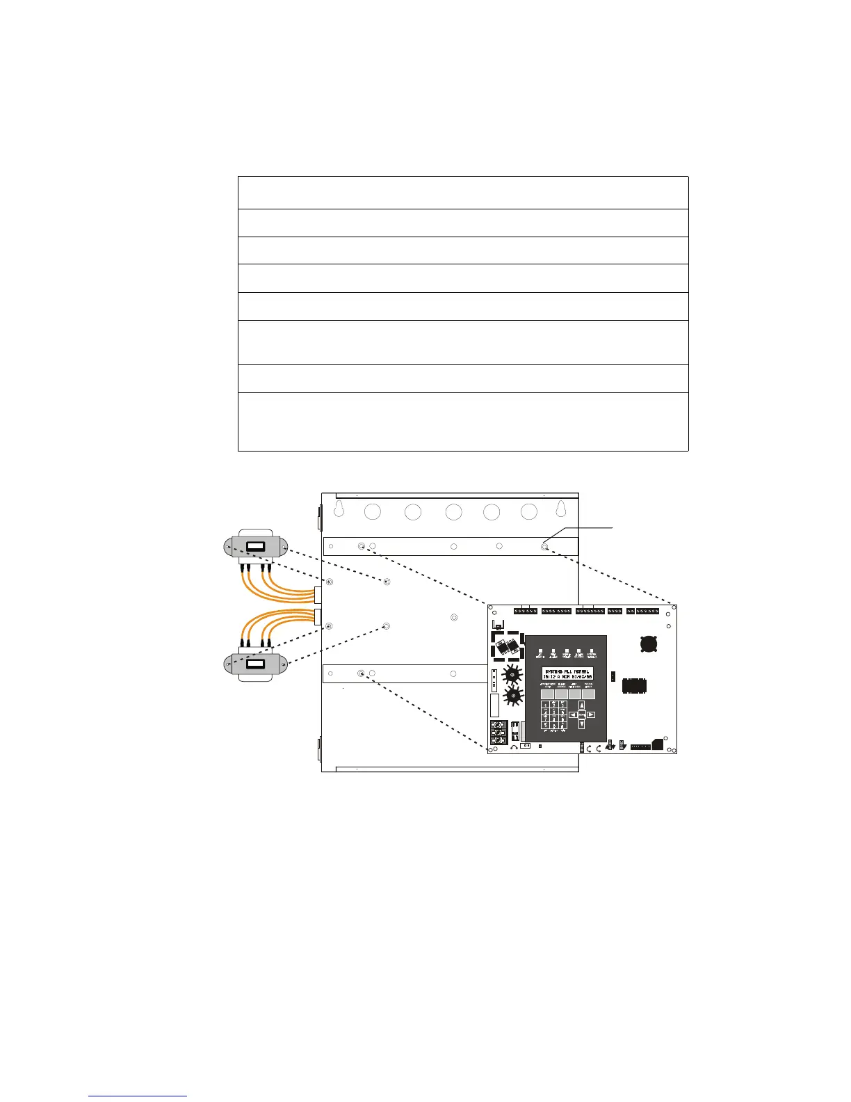
Figure 6 Component Mounting
Step Action
1
Ascertain that backbox area is dry and free of construction dust.
2
Mount the transformer(s) to the backbox studs as shown below.
3
Using the nuts supplied, secure transformer(s) to studs.
4
Install four standoffs in the locations shown below.
5
Position the Main Circuit Board over the backbox rails, aligning
mounting holes, as shown below.
6
Secure in place with four (4) screws. Tighten securely.
7
Plug transformer leads into circuit board connectors:
• Top transformer (supplied) to J17
• Bottom transformer (optional) to J19
24V UNREG 24V NON RS24V RST BELL 2 POWER BELL 1 POWER SUPV AL ARM TROUBLE PC/PRI NTER TERM COMM
GND FAULT
DI SA BL E
TRANSFORMER 1
TRANSFORMER 2
- +
BATTERY
RS-232
PC/PRINTER
RS-485
TERM. MODE
TROUBLE
+ - + - + -
B+ A+ A- B- B+ A+ A- B-
NO C NO NC C NO NC C
A B B+ A+ B- A-
1 COMM 2
ACS
SHIEL D
SLC SL C
OUT+ IN+ OUT- IN-
T
B
4
T
B
2
T
B
1
T
B
3
T
B
7
T
B
5
T
B
6
J16
J6
JP3
JP1
CAUT I ON
HIG H VOLTAG E
J3
TB8
J19
J17
JP4
SW1
SW3
SW2
CAUTION!
HIGH VOLTAGE
GNDFAULT
Afp1assy.cdr
J17
J19
Standoffs
typ (4) plcs
Technical Manuals Online! - http://www.tech-man.com