1. Product Description
Controls and Indicators
12
AFP-100/AFP-100E Instruction PN 51010:C1 02/06/2002
Controls and Indicators
The controls and indicators on the Main Circuit Board include: a membrane panel, five system status
LED indicators, the LCD display, and the local panel sounder.
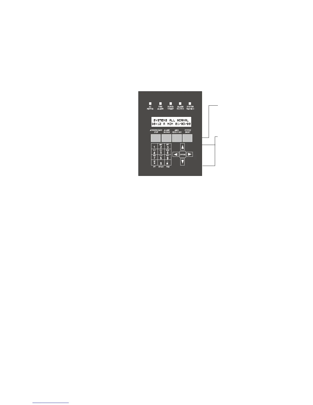
Membrane Panel
Mounted on the main circuit board, the membrane panel includes five system status LED indicators and
a window for the LCD display. The membrane panel, which is visible with the cabinet door closed, has
21 keys, including a 12 key alphanumeric pad similar to a telephone keypad.
Figure 1 Membrane/Display Panel
System Status LED Indicators
System Status LED Indicators are provided to annunciate the following conditions:
LCD Display
The control panel uses a 40-character (2 lines x 20 characters) high viewing angle LCD display with a
character height of 3/16 inches. The display includes a long-life LED backlight that remains
illuminated. If AC power is lost and the system is not in alarm, the LED backlight will turn off to
conserve batteries.
Local Sounder
The control panel has a local sounder to provide separate and distinct pulse rates for alarm, trouble, and
supervisory conditions.
• AC Power (green) • Supervisory (yellow)
• Fire Alarm (red) • Alarm Silence (yellow)
• System Trouble (yellow)
Function keys
Acknowledge/Step
Alarm Silence
Drill
System Reset (lamp test)
Service/program keys:
keys labeled 1 to 9
* (detector) key
# (module) key
0 (recall) key
Four cursor keys (up, down,
right and left/backspace)
Enter key
System Status LED
Indicators
LCD Display
Membrane Panel
9200disp.cdr
Technical Manuals Online! - http://www.tech-man.com