2. Installation
Printer and PC Interface
38
AFP-100/AFP-100E Instruction PN 51010:C1 02/06/2002
Printer and PC Interface
Overview
A remote serial printer or personal computer may be connected to TB7 on the FACP main circuit board.
Switch SW3, located on the bottom center of the main circuit board (see Figure 2 on page 13), must be
set to configure terminal block TB7 for the appropriate device. Placing SW3 in the “up” position [RS-
232 PC/Printer] will allow connection for most 40 and 80 column printers and most IBM compatible
personal computers, including laptops. (Placing SW3 in the “down” position [RS485 Terminal Mode]
will allow connection of most Terminal Mode annunciators.)
Caution: Circuit damage may result if a ground fault exists on the control panel. Do not connect a
printer or PC to the control panel if a ground fault exists on the control panel.
Programming
For printer or PC programming instructions, refer to "System Edit" on page 49.
Installation
Remote printers and PCs require 120 VAC, 60 Hz or 240 VAC, 50 Hz primary power.
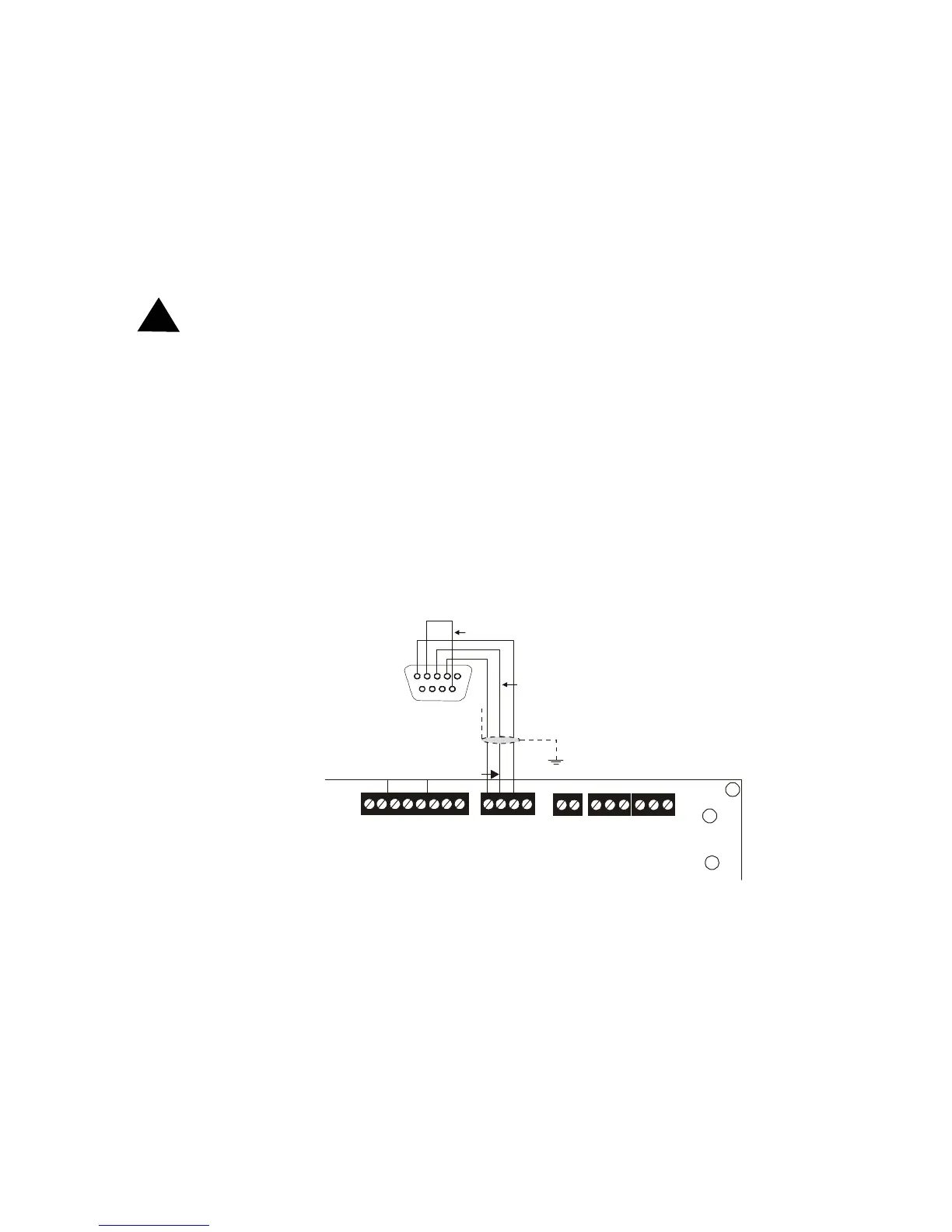
Installation of a printer or PC requires an interface cable prewired to a DB9F connector (see below).
Connect the interface cable to TB7 on the AFP-100 main circuit board and the attached cable to the
EIA-232 serial port on the printer or PC, as shown below. Use a DB25 adapter if a nine pin connector is
not available on your PC or printer.
For this reason, it is important that there
be no pre-existing ground fault on the control panel. Consult the factory for recommended printers.
Figure 17 Printer and Computer Connections
!
SUPV
ALARM
TROUBLE
PC/PRINTER TERM COMM
NO C NO NC C NO NC C
A B B+ A+ B- A-
1 COMM 2
ACS
SHIELD SLC SLC
OUT+ IN+ OUT- IN-
T
B
3
T
B
7
T
B
5
T
B
6
Black
RCV GRND
TX
5 4 3 2 1
9 8 7 6
Green
Jumper
Red
Plug this DB9F connector
into the EIA-232 port of
the printer or PC.
AFP-100
9200tb7.cdr
Cable PN: 75267
Technical Manuals Online! - http://www.tech-man.com