C – 8
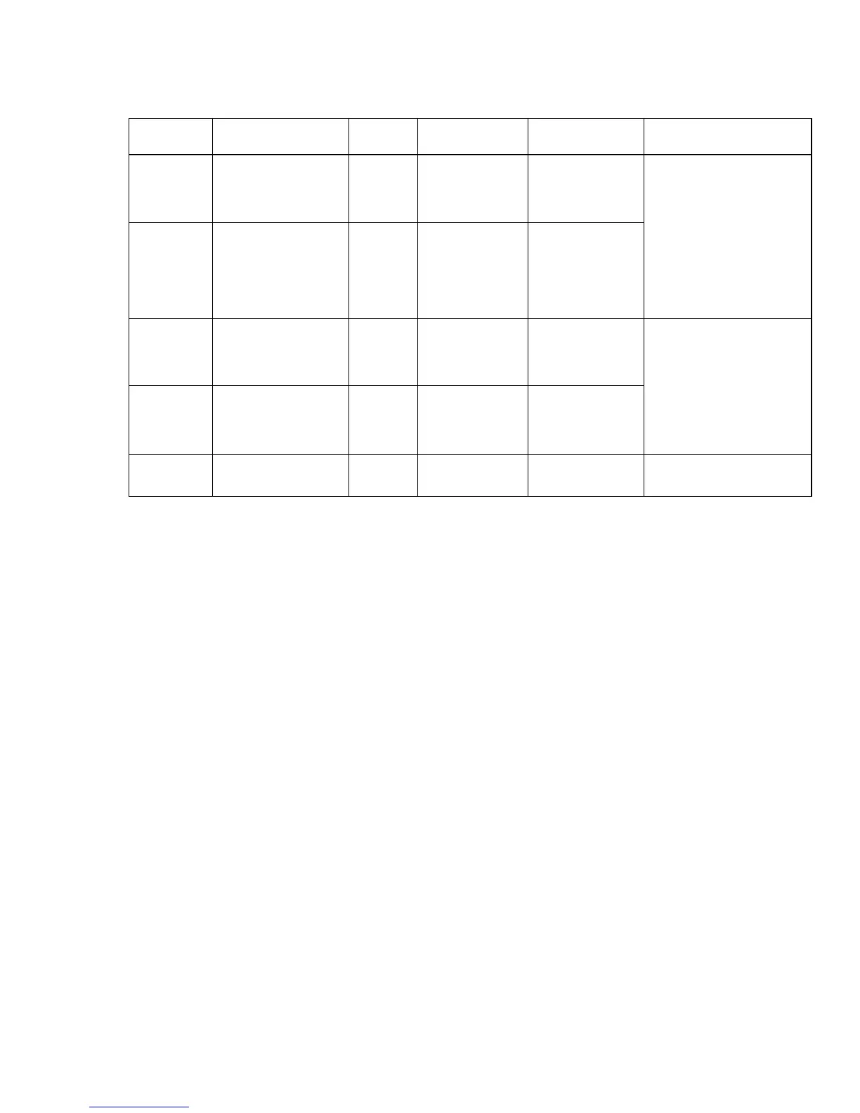
Pin no. Signal Code Direction Connection Function
11** Data mode DM To printer A-A' Indicates that data
can be sent,
printer receives
29 Data mode DM To printer B-B' data after
confirming this
signal as a Space.
12* Terminal RDY TR From A-A' Signal to indicate
printer cannot receive
data in Ready/
30 Terminal RDY TR From B-B' Busy protocol.
printer
19 Signal ground SG — — Signal ground
Notes: Pins 2, 5, 8, 10, 13 to 18, 20, 23, 26, 28 and 31 to 37 are unused.
Notes: * Pins 3 and 21 (SSD), 7 and 25 (RS), or 12 and 30 (TR) can
be set selected as Busy lines.
** DM signal valid/invalid can be set by menu.
☞