C – 5
Serial Interfacing (RS-232C)
To construct a cable for an RS-232C serial configuration, you will need:
● DB25P equivalent 25-pin plug, shell equivalent to DB-C2-J9.
● Beldon (or equivalent) SHIELDED cable with twisted pair conductors. Must be
UL and CSA approved. The cable MUST be shielded.
● The printer has a 25-pin DB-255 receptacle.
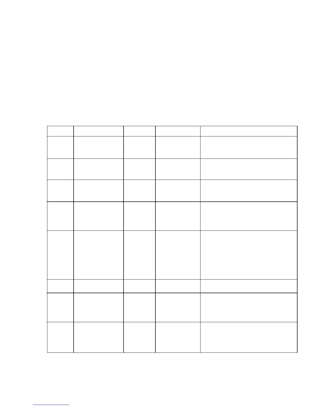
Pin Description
Pin Signal Symbol Direction Description
1 Frame ground FG — Connected to the printer frame
(frame ground).
2 Transmitted TD From printer Serial data signal transmitted
data from printer.
3 Received data RD To printer Serial data signal received by
printer.
4* Request to send RTS From printer Signal to indicate that the
printer is not ready for receiving
data in Ready/Busy protocol.
6** Data set ready DSR To printer Signal to notify printer that
transmitter is ready for
transmission. Printer receives
data after confirming the signal
as a HIGH.
7 Signal ground SG — Signal ground.
11* Supervisory SSD From printer Signal to indicate the printer
send data is not ready for receiving data
in Ready/Busy protocol.
20* Data terminal DTR From printer Signal to indicate that the
printer is not ready for receiving
data in Ready/Busy protocol.
Note: Pins 5, 8 to 10, 12 to 19, 21 to 25 are unused.
Notes: * SSD signal output can be selected between 4,11,20 by menu.
** DSR signal valid/invalid can be set by menu.
☞