DMTA-10009-01EN [U8778346], Rev. D, November 2016
List of Figures
95
List of Figures
Figure i-1 The warning symbol between the T/R connectors .......................................... 1
Figure i-2 Labels and symbols are attached to the instrument ....................................... 2
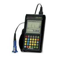
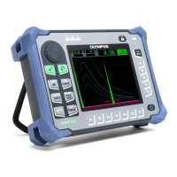
Figure i-3 The 38DL PLUS instrument ............................................................................. 17
Figure 1-1 Measuring thicknesses with the 38DL PLUS ................................................. 20
Figure 1-2 The 38DL PLUS hardware components ......................................................... 23
Figure 1-3 The 38DL PLUS connections ............................................................................ 24
Figure 1-4 The top end connectors ..................................................................................... 25
Figure 1-5 The connectors behind the I/O door ............................................................... 25
Figure 1-6 The 38DL PLUS keypads .................................................................................. 26
Figure 2-1 The power indicator for battery and AC operation ...................................... 31
Figure 2-2 Connecting the charger/adaptor ...................................................................... 32
Figure 2-3 Connecting the DC power plug ....................................................................... 33
Figure 2-4 Opening the battery compartment .................................................................. 36
Figure 2-5 Selecting the new battery type ......................................................................... 37
Figure 3-1 The main elements of the measurement screen ............................................ 39
Figure 3-2 The ID bar ........................................................................................................... 40
Figure 3-3 Example of other elements appearing on the measurement screen ........... 41
Figure 3-4 The loss-of-signal (LOS) indicator ................................................................... 41
Figure 3-5 Menu and submenu example .......................................................................... 42
Figure 3-6 Parameter screen example ................................................................................ 43
Figure 3-7 Example of the virtual keyboard ..................................................................... 45
Figure 3-8 The character cycle of the traditional text edit method ............................... 46
Figure 4-1 Selecting the user interface language ............................................................. 50
Figure 4-2 Selecting clock parameters ............................................................................... 51
Figure 4-3 The DISPLAY SETTINGS screen ..................................................................... 52
Figure 4-4 Example of the indoor and the outdoor color schemes ............................... 53
Figure 4-5 Examples of the rectification modes ............................................................... 54
Figure 4-6 Examples of waveform trace modes ............................................................... 56
Figure 4-7 The range of the waveform display ................................................................ 57
Figure 4-8 Comparing normal and zoomed display in mode 1 .................................... 59

 Loading...
