• When the Drive Programming program is stopped, the data of the analog output terminal
variables before the program stop is retained. When the program execution is started again,
the process begins with the retained data. However, the outputs with the Drive Programming
not set are controlled as the inverter's analog outputs independently of the program.
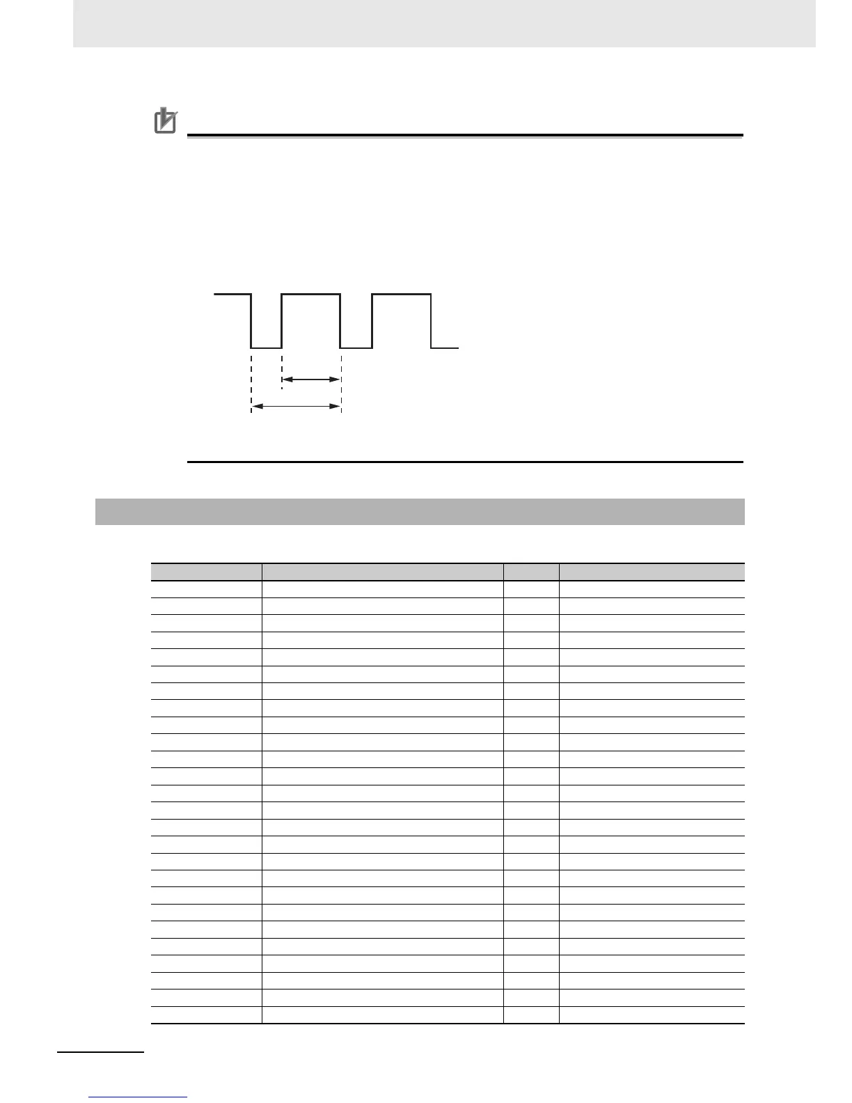
• The multi-function digital output (PWM output) FM terminal provides PWM signal outputs.
The terminal outputs the value of 0.00 to 100.00% (variable) as the pulse width (duty ratio
t/T) in a 6.4 ms cycle.
9-4-2 Multi-function Input Variables
Function variable Description R/W Reference
UP Upward RUN R/W C001 to C007 00
DWN Downward RUN R/W C001 to C007 01
SPD1 Multi-speed 1 setting R/W C001 to C007 02
SPD2 Multi-speed 2 setting R/W C001 to C007 03
SPD3 Multi-speed 3 setting R/W C001 to C007 04
SET 2nd Control R/W C001 to C007 08
FRS Free-run stop R/W C001 to C007 11
EXT External trip R/W C001 to C007 12
SFT Soft lock R/W C001 to C007 15
RS Reset R/W C001 to C007 18
OLR Change OL-level R/W C001 to C007 32
TL Torque limit enable R/W C001 to C007 33
TRQ1 Change Torque limit 1 R/W C001 to C007 34
TRQ2 Change Torque limit 2 R/W C001 to C007 35
PCLR Clear the current position R/W C001 to C007 40
KHC Kwh clear R/W C001 to C007 46
X(00) to X(11) Drive Programming MI1 to MI12 R/W C001 to C007 49 to 60
EMP Em-Power operation R/W C001 to C007 61
INSP Inspection R/W C001 to C007 62
RL Releveling R/W C001 to C007 63
COK Contactor check signal R/W C001 to C007 64
BOK Brake check signal R/W C001 to C007 65
FP1 to FP6 Floor position 1 to 6 R/W C001 to C007 66 to 71
PAL Auto learning data latch trigger R/W C001 to C007 72
TCL Torque bias latch trigger R/W C001 to C007 73
LVS Levelling signal R/W C001 to C007 74
t
T

 Loading...


