5 Drive Programming User Variables
5 - 14
Drive Programming User’s Manual (I580-E2)
5-5 Inverter Monitor Variables
You can use the inverter's internal monitor function and status monitor function as the variables of the
Drive Programming function.
For details on each monitor function, refer to the MX2 User's Manual (I570-E2) or the RX User's Manual
(I560-E2).
Note that the data unit used for the inverter may be different from that for Drive Programming. Be sure
to use the following units.
MX2 and RX
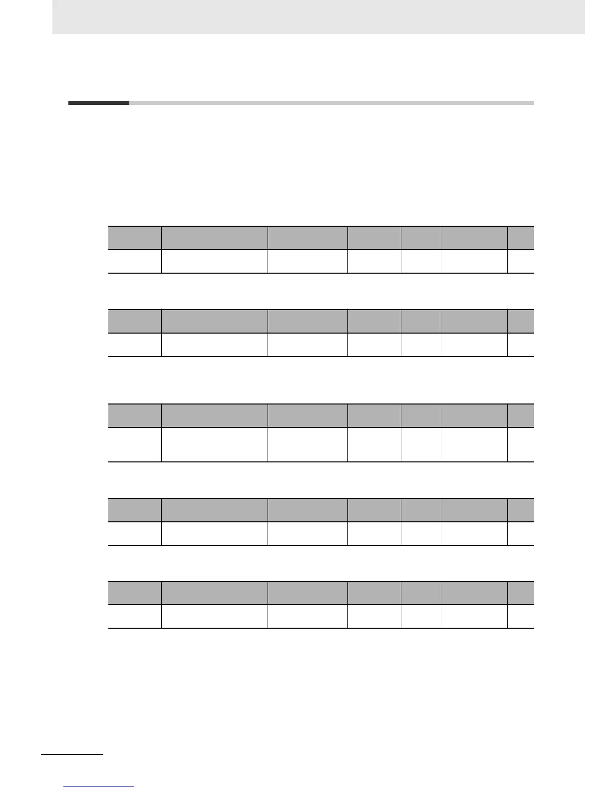
Use this function to monitor the inverter output frequency. The monitored data is equivalent to the data
of the Output Frequency Monitor (d001). This variable is read-only.
Use this function to monitor the inverter output current. The monitored data is equivalent to the data of
the Output Current Monitor (d002). The data is displayed in increments of 0.1% as a percentage of the
rated current of the inverter. This variable is read-only.
Use this function to monitor the operation direction of the inverter. The monitored data is equivalent to
the data of the RUN Direction Monitor (d003). This variable is read-only.
Use this function to monitor the PID feedback value. The monitored data is equivalent to the data of the
PID Feedback Value Monitor (d004). This variable is read-only.
Use this function to monitor the output frequency after conversion. The monitored data is equivalent to
the data of the Output Frequency Monitor (After Conversion) (d007). This variable is read-only.
Function
variable
Description Data range
Default
data
Unit Data size R/W
FM
Output Frequency Monitor
[d001]
0 to 40,000 0.01 Hz Unsigned
1 word
R
Function
variable
Description Data range
Default
data
Unit Data size R/W
Iout Output Current Monitor
(d002)
0 to 9,999 0.1% Unsigned
1 word
R
Function
variable
Description Data range
Default
data
Unit Data size R/W
Dir RUN Direction Monitor
(d003)
0: Stop
1: Forward
2: Reverse
Unsigned
1 word
R
Function
variable
Description Data range
Default
data
Unit Data size R/W
PID-FB
PID Feedback Value Monitor
(d004)
0 to 133,333 0.01% Unsigned
2 words
R
Function
variable
Description Data range
Default
data
Unit Data size R/W
F-CNV
Output Frequency Monitor
(After Conversion) (d007)
0 to 3,999,600 0.01 Unsigned
2 words
R

 Loading...


