5 Drive Programming User Variables
5 - 20
Drive Programming User’s Manual (I580-E2)
5-7 Multi-function Output Variables
You can execute the functions which can be allocated to the multi-function output terminals by using the
Drive Programming program. The following variables correspond to the functions which can be allo-
cated to the multi-function output terminals.
Setting each variable to 1 (ON) or 0 (OFF) causes the same operation as when the multi-function out-
put function turns the multi-function output terminal ON/OFF. You can monitor the status on the pro-
gram even if you do not set each function in the parameters Multi-function Output Selection (MX2:
C021 and C022/RX: C021 to C025 ) or Multi-function Relay Output (MA, MB) Function Selection
(C026). The Reference column in the following table shows the function setting data for the inverter. For
details on each function,
refer to the MX2 User's Manual (I570-E2) or the RX User's Manual (I560-E2)
.
When the Drive Programming program is stopped, the status of the multi-function output vari-
ables is not retained but updated according to the actual function status.
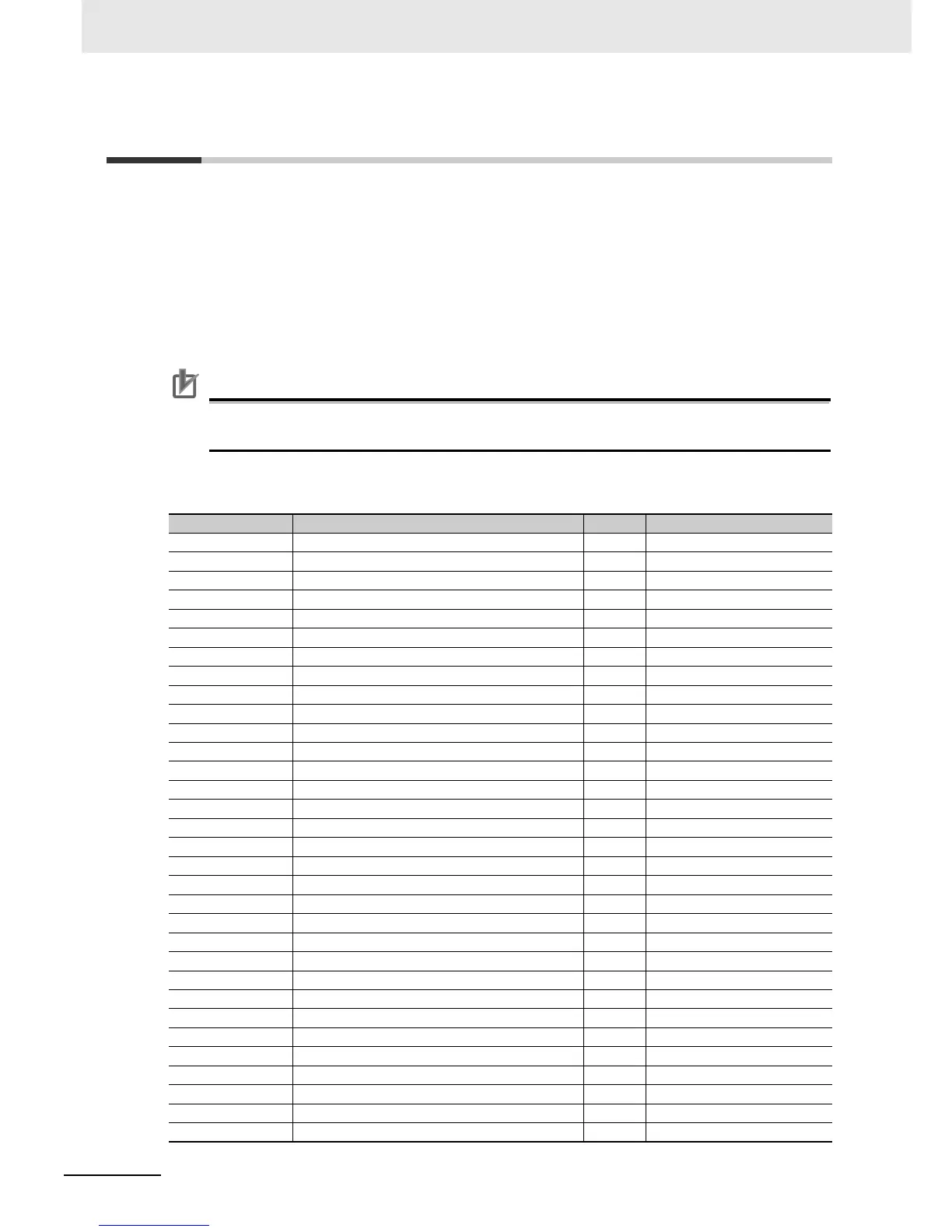
MX2 and RX
Function variable Description R/W Reference
RUN Signal during RUN R C021 to C026 00
FA1 Constant speed arrival signal R C021 to C026 01
FA2 Set frequency exceeded signal R C021 to C026 02
OL Overload warning R C021 to C026 03
OD Excessive PID deviation R C021 to C026 04
AL Alarm signal R C021 to C026 05
FA3 Set-frequency only signal R C021 to C026 06
OTQ Overtorque/Undertorque signal R C021 to C026 07
UV Signal during undervoltage R C021 to C026 09
TRQ Torque limit R C021 to C026 10
RNT RUN time over R C021 to C026 11
ONT Power ON time over R C021 to C026 12
THM Electronic thermal warning R C021 to C026 13
BRK Brake release R C021 to C026 19
BER Brake error R C021 to C026 20
ZS 0 Hz detection signal R C021 to C026 21
DSE Excessive speed deviation R C021 to C026 22
POK Position ready R C021 to C026 23
FA4 Set frequency exceeded signal 2 R C021 to C026 24
FA5 Set-frequency only signal 2 R C021 to C026 25
OL2 Overload warning 2 R C021 to C026 26
ODc Analog FV disconnection detection R C021 to C026 27
OIDc Analog FI disconnection detection R C021 to C026 28
FBV PID feedback comparison signal R C021 to C026 31
NDc Communications disconnection detection R C021 to C026 32
LOG1 Logic operation output 1 R C021 to C026 33
LOG 2 Logic operation output 2 R C021 to C026 34
LOG 3 Logic operation output 3 R C021 to C026 35
WAC Capacitor life warning signal R C021 to C026 39
WAF Cooling fan life warning signal R C021 to C026 40
FR Starting contact signal R C021 to C026 41
OHF Cooling fin overheat warning R C021 to C026 42

 Loading...


