5 - 17
5 Drive Programming User Variables
Drive Programming User’s Manual (I580-E2)
5-6 Multi-function Input Variables
5
5-6 Multi-function Input Variables
You can execute the functions allocated to the multi-function input terminals by the Drive Programming
program. The following variables correspond to the functions which can be allocated to the multi-func-
tion input terminals.
If any of the variables is set to 1 (ON), the corresponding function is enabled in the same way as when
the multi-function input terminal is turned ON.
If any of the variables is set to 0 (OFF), the corresponding function is disabled. You can execute the
functions by the program even if you do not allocate the functions to the Multi-function Input Selection
(MX2: C001 to C007/RX: C001 to C008). The Reference column in the following table shows the func-
tion setting data for the inverter. For details on each function,
refer to the MX2 User's Manual (I570-E2) or
the RX User's Manual (I560-E2)
.
Example
If you set FW (forward) to 1, the forward RUN command is executed.
FW: 1 the inverter starts forward operation.
FW: 0 the inverter stops forward operation and starts deceleration.
• If the Drive Programming program is stopped, the data of the multi-function input variables is
not retained but cleared to zero.
• The variable FW (forward) and RV (reverse) are enabled only when the inverter's RUN Com-
mand Selection (A002) is set to 01 (Control circuit terminal block). The inverter does not
operate with other setting options.
• Even if you set the variable FW (forward) or RV (reverse) to 1 immediately after turning on
the power supply, the setting is ignored and neither forward or reverse operation is per-
formed. Set 0, and then set 1 again. To avoid this operation, create a program that has one
second of wait time after turning on the power supply, with such as “wait” command.
• Only for the variable AT (Analog input switching), it is required to set the Multi-function Input
Selection (MX2: C001 to C007/RX: C001 to C008). To use the variable AT (Analog input
switching), set one of the Multi-function Input Selection parameters to 16 (AT: Analog input
switching). If you do not set it, the expected operation is not performed even if the variable AT
(Analog input switching) is set to 1 in the program.
• The relationship between the inverter's multi-function input function set in the Multi-function
Input Selection and the multi-function input variable is logical OR.
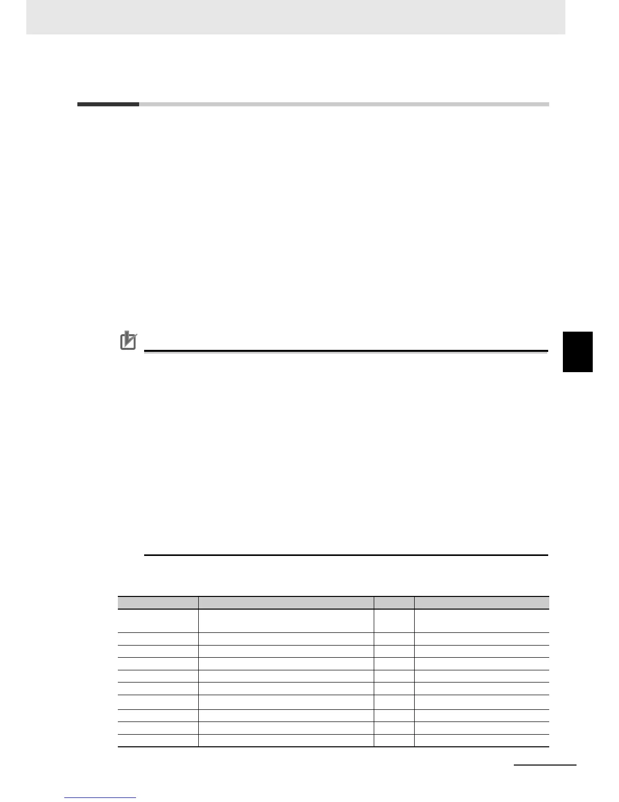
MX2 and RX
Function variable Description R/W Reference
FW Forward R/W MX2: C001 to C007 00
RX: FW terminal
RV Reverse R/W C001 to C008 01
CF1 to CF4 Multi-step speed setting binary 1 to 4 R/W C001 to C008 02 to 05
JG Jogging R/W C001 to C008 06
DB External DC injection braking R/W C001 to C008 07
SET 2nd Control R/W C001 to C008 08
TCH (2CH)
*1
2-step acceleration/deceleration R/W C001 to C008 09
FRS Free-run stop R/W C001 to C008 11
EXT External trip R/W C001 to C008 12
USP Power recovery restart prevention function R/W C001 to C008 13

 Loading...


