5 Drive Programming User Variables
5 - 8
Drive Programming User’s Manual (I580-E2)
You can use the inverter's frequency reference input (analog voltage input) FV terminal and the fre-
quency reference input (analog current input) FI terminal as the analog input terminal variables XA(0)
and XA(1) of the Drive Programming function.
For the 3G3RX Series Inverter, it is also possible to use the frequency reference auxiliary input (analog volt-
age input) FE terminal as the analog input terminal variable XA(2) of the Drive Programming function.
You can continuously monitor the status of the analog inputs regardless of the parameter settings.
• The analog input terminal variables XA(0) and XA(1) are unsigned 1-word variables, and XA(2) is a
signed 1-word variable. This variable is read-only.
• The variables are displayed in increments of 0.01% as a percentage of the maximum analog input
10 V or 20 mA.
• You can allocate inverter functions to the analog input terminals with the inverter parameters as
shown below. Select a function in each parameter.
If you use the analog input terminals only for the Drive Programming, do not select the analog input
terminal in the following parameters.
MX2: A001, A201, A005, A076, A079, A141, A142, b040, and P033
RX: A001, A005, A006, A076, A079, A141, A142, b040, and P033
• To adjust the analog inputs, use the following inverter parameters: (FV: A011 to A016, FI: A101 to
A105, and FE: A111 to A114).
When the Drive Programming program is stopped, the status of the analog input terminal vari-
ables is not retained but updated according to the status of actual input terminals.
You can use the inverter's multi-function digital output (PWM output) MP terminal and the multi-function
analog output (voltage output) AM terminal as the analog output terminal variables YA(0) and YA(1) of
the Drive Programming function.
For the 3G3RX Series Inverters, it is also possible to use the multi-function analog output (current output)
AMI terminal as the analog output terminal variables YA(2) of the Drive Programming function.
You can continuously monitor the status of the analog outputs regardless of the parameter settings.
To control the analog outputs via the Drive Programming function, select Drive Programming for the
setting of the inverter parameters MP Selection (C027), AM Selection (C028) and AMI Selection
(C029).
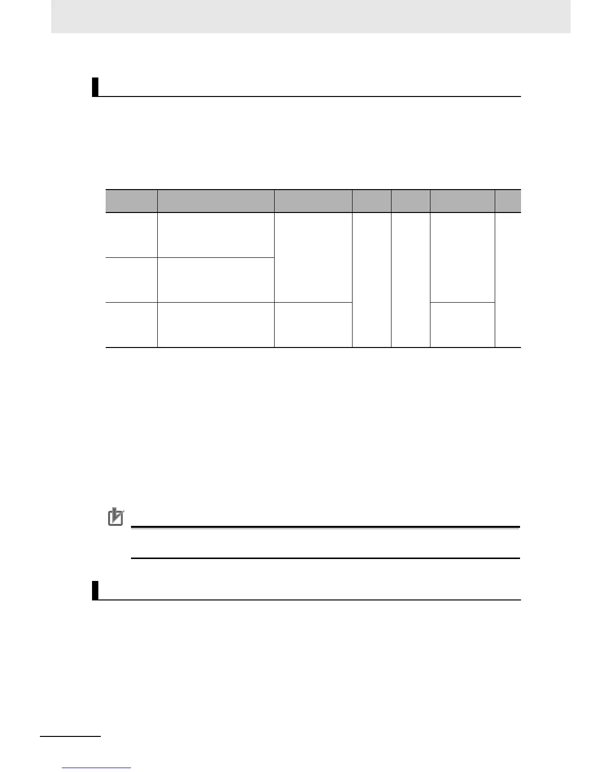
Analog Input Terminal Variables XA(0) to XA(2)
Function
variable
Description Data range
Default
data
Unit Data size R/W
XA(0) MX2 and RX:
Analog input terminal variable
(between FV and FC termi-
nals: 0 to 10 V input)
0 to 10,000 0 0.01% Unsigned
1 word
R
XA(1) MX2 and RX:
Analog input terminal variable
(between FI and FC termi-
nals: 4 to 20 mA input)
XA(2) RX only:
Analog input terminal variable
(between FE and FC termi-
nals: 10 to 10 V input)
10,000 to 10,000 Signed
1 word
Analog Output Terminal Variables YA(0) to YA(2)

 Loading...


