57
Basic Concepts Section 2-1
Mnemonic Execution Order
PLCs execute ladder programs in the order the mnemonics are entered so
instructions may not operate as expected, depending on the way rungs are
written. Always consider mnemonic execution order when writing ladder dia-
grams.
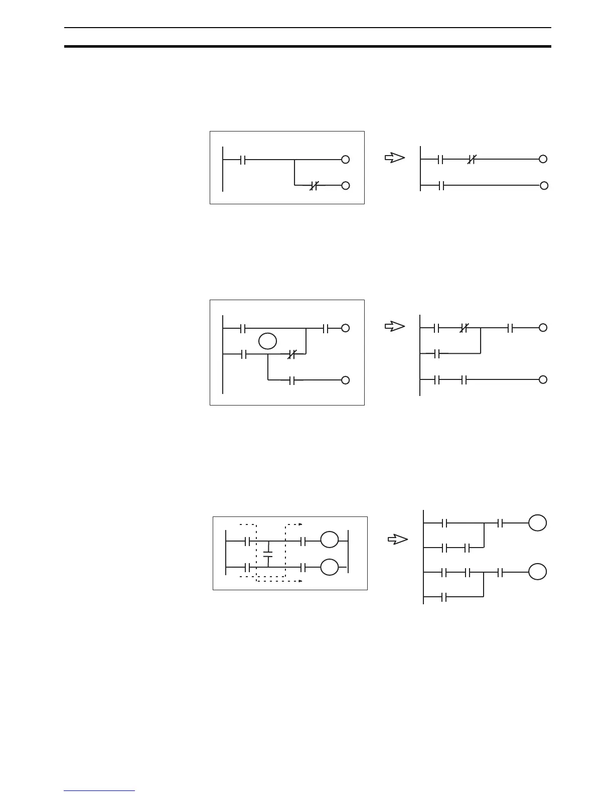
Example: CIO 000210 in the above diagram cannot be output. By rewriting
the rung, as shown above, CIO 000210 can be turned ON for one cycle.
Rungs Requiring Rewriting
PLCs execute instructions in the order the mnemonics are entered so the sig-
nal flow (power flow) is from left to right in the ladder diagram. Power flows
from right to left cannot be programmed.
Example: The program can be written as shown in the diagram at the left
where TR0 receives the branch. The same value is obtained, however, by the
rungs at the right, which are easier to understand. It is recommended, there-
fore, that the rungs at the left be rewritten to the rungs at the right.
Rewrite the rungs on the left below. They cannot be executed.
The arrows show signal flow (power flow) when the rungs consist of control
relays.
0000
00
0010
00
0000
00
0000
00
0002
10
0002
10
0010
00
0010
00
0010
00
0000
00
0000
03
0002
11
0000
01
0002
11
TR0
0002
12
0000
01
0000
02
0002
12
0000
04
0000
02
0000
03
0000
00
0000
04
0000
01
A
C
B
D
R1
R2
E
A
C
B
D
E
A
C
E
R1
R2