317
Changing the Timer/Counter PV Refresh Mode Section 6-4
6-4-4 BCD Mode/Binary Mode Mnemonics and Data
BCD Mode/Binary Mode Mnemonics
Binary mode mnemonics are indicated by the suffix X added to the BCD mne-
monic.
Example: Mnemonics for the HUNDRED-MS TIMER instruction
BCD mode: TIM
Binary mode: TIMX
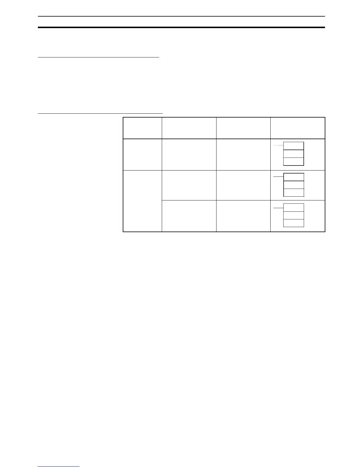
BCD Mode/Binary Mode Data Display
Note When using the CX-Programmer in either BCD or binary mode, if the numeri-
cal value is input without including the input/display symbol # or & indicating
the constant, (e.g., TIM 0000 0010), the timer/counter set value will be input
as an address (e.g., the value in CIO word 0010 will be used as the set value).
6-4-5 Restrictions
• BCD mode and binary mode cannot be used together in the same CPU
Unit.
• When the Programming Console is used to create a new user program, or
to clear memory, the timer/counter PV refresh mode is fixed in BCD
mode.
• When CX-Programmer Ver. 3.0 is used to place the CPU Unit online, the
set value that is stored in the CPU Unit’s user memory for the timer/
counter PV refresh mode will be automatically used. If the CPU setting is
different from the setting for the CX-Programmer project, an error will
occur, and the online connection will not be possible. The following mes-
sage will be displayed.
PLC property Meaning of input
and display
symbols
Setting range Example: Timer
number: 0000,
Set value: 10 s
BCD mode The # symbol indi-
cates the instruction
value (a BCD value
when BCD mode is
used)
#0000 to #9999
or
#00000000 to
#99999999
Binary mode The & symbol indi-
cates a decimal
value.
&0 to &65535
or
&0 to &4294967295
The # symbol indi-
cates the instruction
value (a hexadeci-
mal value when BCD
mode is used.)
#0000 to #FFFF
or
#0000 to #FFFFFFFF
TIM
0000
#0100
TIMX
0000
&100
TIMX
0000
#64