CHAPTER 6 USING THE COMMUNICATIONS FUNCTION
E5CK
6–8
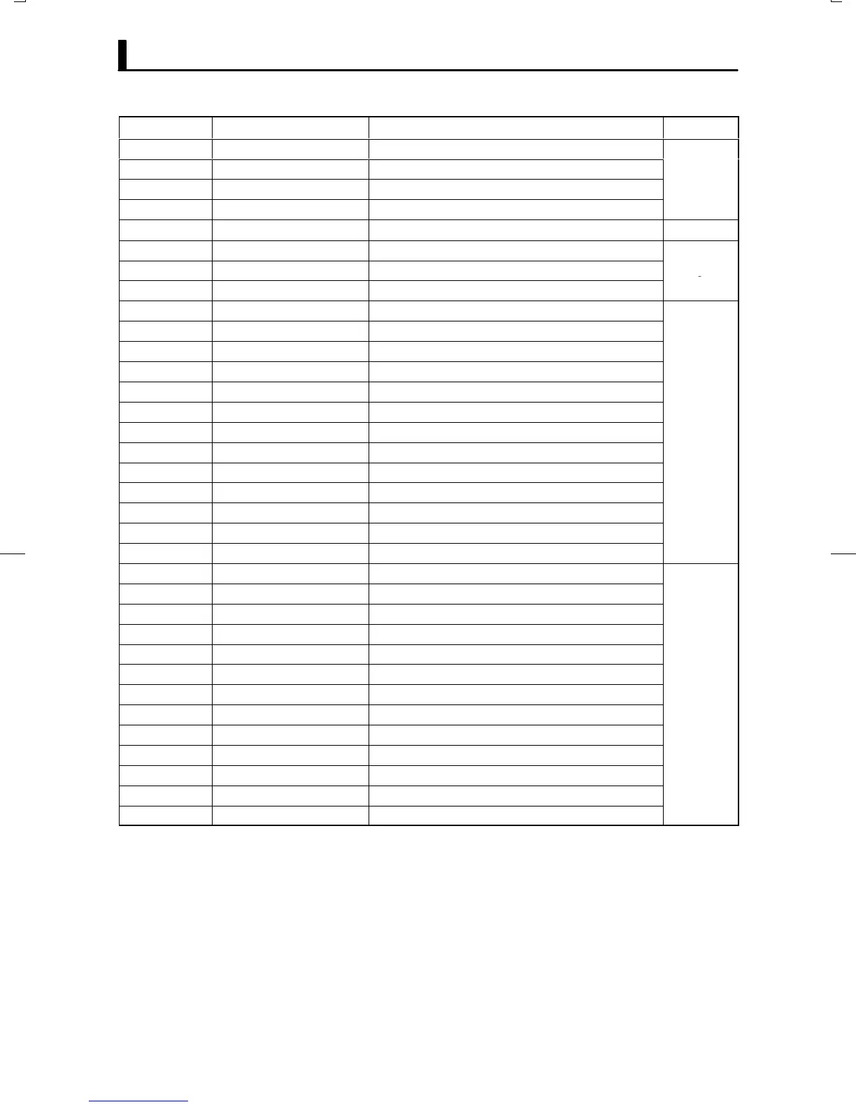
Parameter No. Parameter Data Setting and Monitor Range Mode
00 PV monitor *1 *2 Scaling lower limit -10% to scaling upper limit +10%
01 Set point *1 Set point lower limit to set point upper limit
04 MV monitor (heat) *1 -5.0 to 105.0
eve
14 Valve opening monitor *1 -10.0 to 110.0 Level 0
02 Alarm value 1 -1999 to 9999
03 Alarm value 2 -1999 to 9999 Program
41 Alarm value 3 -1999 to 9999
19 Proportional band 0.1 to 999.9
20 Integral time 0 to 3999
21 Derivative time 0 to 3999
22 Cooling coefficient 0.01 to 99.99
09 Dead band -19.99 to 99.99
23 Manual reset value 0.0 to 100.0 Level 1
06 Hysteresis (heat) 0.01 to 99.99
43 Hysteresis (cool) 0.01 to 99.99
07 Control period (heat) 1 to 99
08 Control period (cool) 1 to 99
46 LBA detection time 0 to 9999
47 MV at reset *5 -5.0 to 105.0
48 MV at PV error *5 -5.0 to 105.0
50 MV upper limit *3 MV lower limit +0.1 to 105.0
49 MV lower limit *4 -5.0 to MV upper limit -0.1
51 MV change rate limit 0.0 to 100.0
56 Input digital filter 0 to 9999 Level 2
25 Alarm 1 hysteresis 0.01 to 99.99
26 Alarm 2 hysteresis 0.01 to 99.99
52 Alarm 3 hysteresis 0.01 to 99.99
53 Input shift upper limit -199.9 to 999.9
54 Input shift lower limit -199.9 to 999.9
*1 Possible only during reading
*2 During temperature input, the range becomes the range of use of the selected sensor.
*3 During heating and cooling control, the range becomes 0.0 to 105.0.
*4 During heating and cooling control, the range becomes Ć105.0 to 0.0.
*5 During heating and cooling control, the range becomes Ć105.0 to 105.0.
*3