CHAPTER 7 CALIBRATION
E5CK
7–12
7.6 Checking Indication Accuracy
JChecking indication accuracy
Ă• After calibrating input, be sure to check indication accuracy to make
sure that the E5CKĆT controller has been correctly calibrated.
Ă• Operate the E5CKĆT controller in the PV/SP monitor (level 0 mode)
mode.
Ă• Check the indication accuracy at the upper and lower limits and midĆ
point.
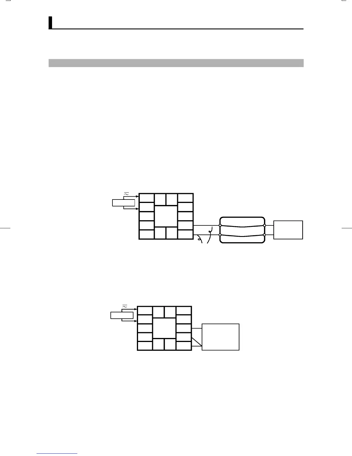
Ă• Preparation
The following figure shows the required device connection. Make sure
that the E5CKĆT controller and cold junction compensator are conĆ
nected by a compensating conductor for the input type (thermocouple)
that is to be used during actual operation.
10
9
8
7
6
5
4
3
2
1
1413
1211
STV
Cold junction
compensator
Compensation
conductor
AC100-240V
(AC/DC24V )
~
SOURCE
Ă• Operation
Make sure that the cold junction compensator is at 0C, and set STV outĆ
put to the voltage equivalent to the starting power of the check value.
Ă• Preparation
The following figure shows the required device connection.
10
9
8
7
6
5
4
3
2
1
1413
1211
6-dial
AC100-240V
(AC/DC24V )
~
SOURCE
Ă• Operation
Set the 6Ćdial to the resistance equivalent to the check value.
F Thermocouple
F Platinum resis-
tance thermome-
ter