APPENDIX
E5CK
A–8
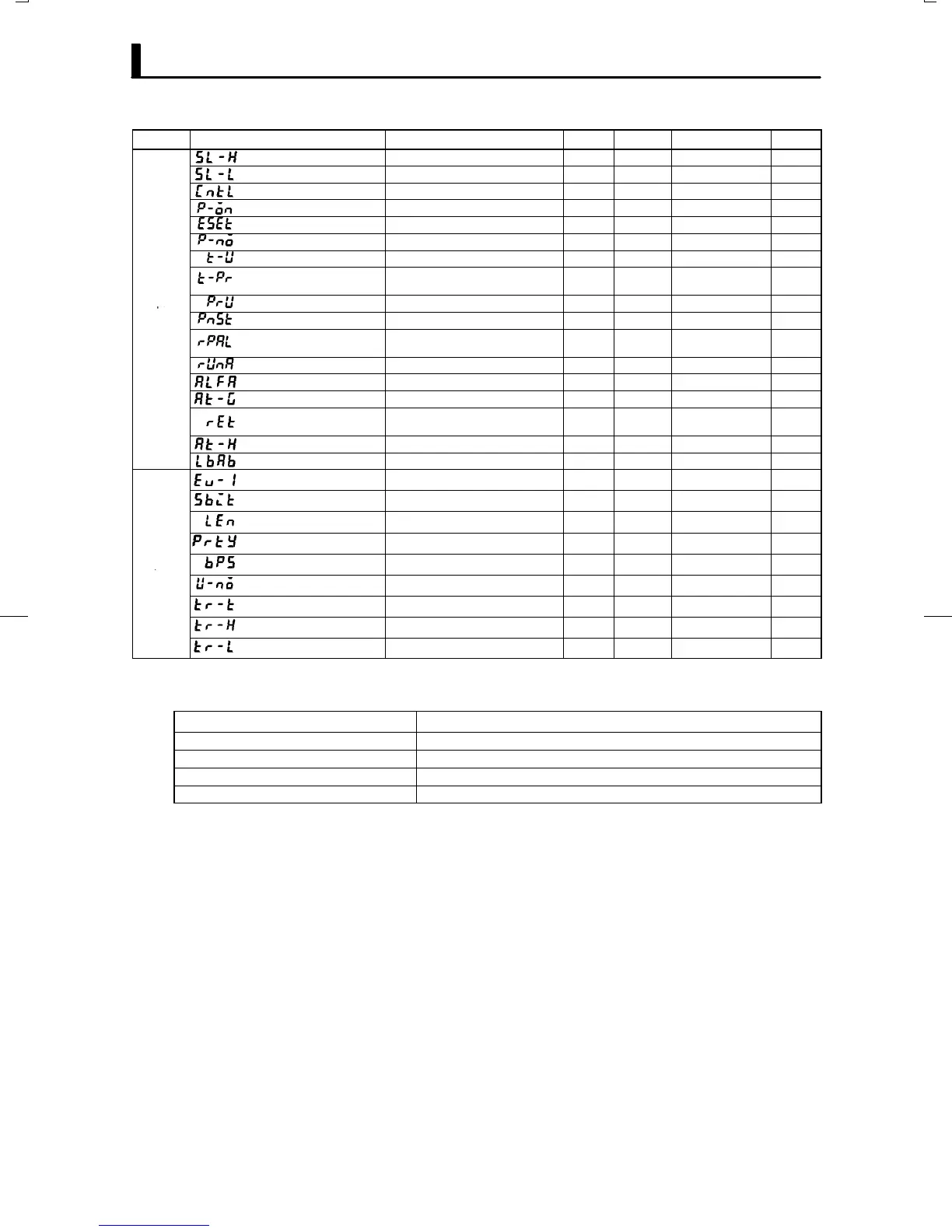
Mode Parameter Name Setting Range Unit Default Remarks Setting
Set point upper limit
Set point lower limit +1 to scaling upper limit
EU 1300
Set point lower limit
Scaling lower limit to Set point upper limit -1
EU -200
PID / ON/OFF PID / ON/OFF None PID
Operation at power ON CON/RST/RUN/MAN None CON
End condition RST/SP None RST
Number of patterns 1 to 4 None 1
Program time unit HHMM/MMSS None HHMM
Step time/Rate of rise pro-
gramming
TIME/PR None OFF
Expan-
Time unit of ramp rate M/H None OFF
sion
PV start PV/SP None SP
Alarm during ramp step en-
able
ON/OFF None ON
Run all enable ON/OFF None OFF
α 0.00 to 1.00 None 0.65
AT calculated gain 0.1 to 10.0 None 1.0
Automatic return of display
mode
0 to 99 Sec 0
AT hysteresis 0.1 to 9.9 %FS 0.2
LB detection width 0.0 to 999.9 %FS 0.2
Event input assignment 1
NON/RST/MAN/HOLD/ADV/PTN0 to 1
None NON
Communication stop bit 1/2 bit 2
Communication data length 7/8 bit 7
Communication parity NONE/EVEN/ODD None EVEN
Option
Communication baud rate 1.2/2.4/4.8/9.6/19.2 kbps 9.6
Communication unit No. 0 to 99 None 0
Transfer output type SP/PV/O/C-O None SP
Transfer output upper limit *10 *10 10
Transfer output lower limit *10 *10 *10
*9 When temperature input is selected, the range of the sensor selected in the input type" parameter (setup mode) corresponds to the
scaling upper and lower limit value.
*10 Set the transfer output type parameter according to the following table.
Transfer Output Type
Transfer Output Lower Limit to Transfer Output Upper Limit
SP :Present SP -1999 to 9999
PV :Process value -1999 to 9999
O :Manipulated variable (heat) -5.0 to 105.0% (standard control), 0.0 to 105.0% (heating and cooling control)
C-O :Manipulated variable (cool) 0.0 to 105.0%
Default : [SP]
*9
*9