PARAMETER OPERATIONS LIST
E5CK
A–11
PARAMETER OPERATIONS LIST
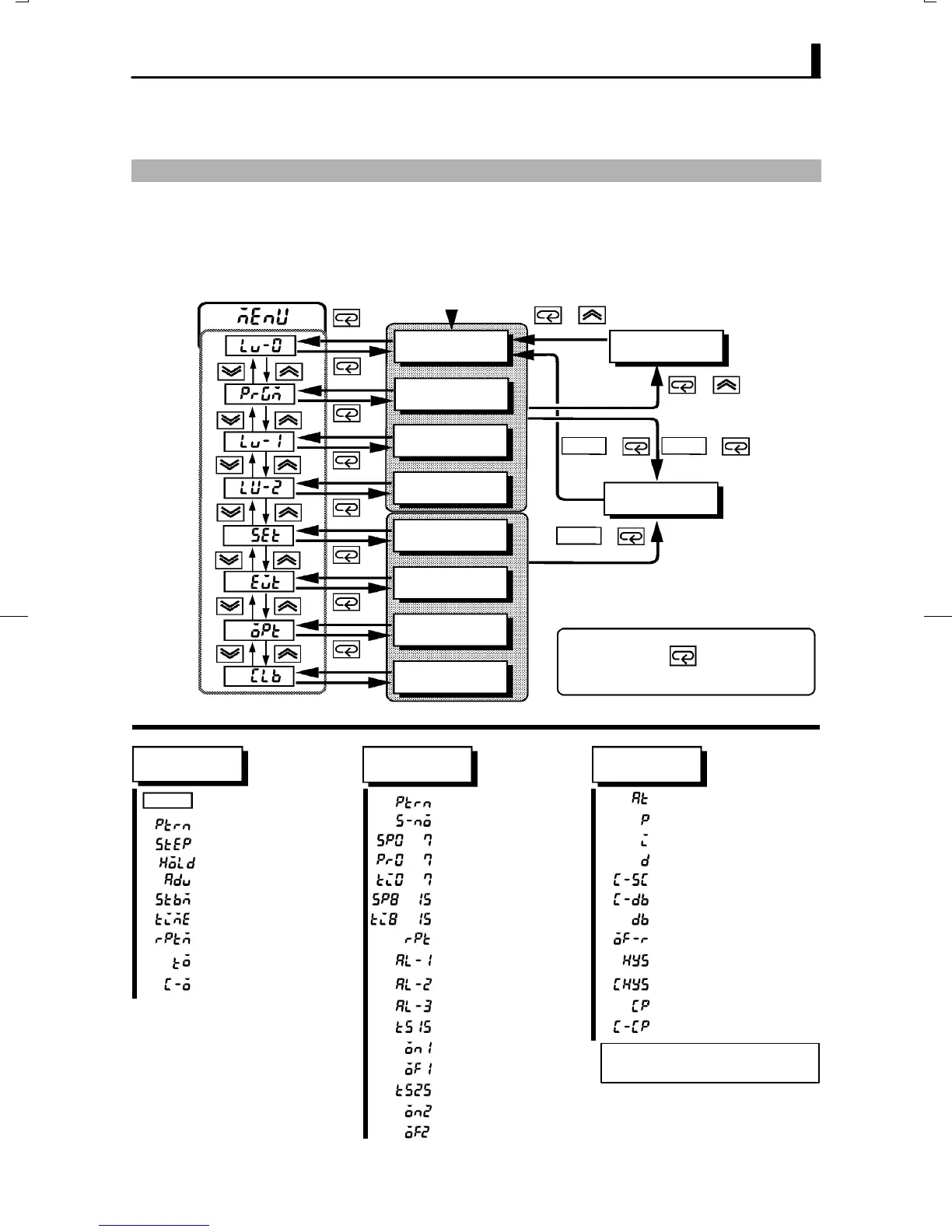
Ă• Switching to modes other than the manual or protect mode is carried out by mode selection in the
menu display.
Ă• The figure below shows all parameters in the order that they are displayed. Some parameters are
not displayed depending on the protect mode setting and conditions of use.
Level 0
Program
1 second min.
Manual mode
Protect mode
Parameters in a mode can be
switched by the key. The param-
eter following the last parameter is the
top parameter of the mode.
Power ON
1 second min.
1 second min.
1 second min.
1 second min.
1 second min.
1 second min.
1 second min.
1 second min.
Level 1
Level 2
Setup mode
Expansion
mode
Option mode
Calibration
mode
1 second min.
1 second min.1 second min.
1 second min.
+
+
+
+
RUN/RST
RUN/RST
RUN/RST
Level 0
Program
Level 1
PV/Present SP Pattern No. AT Execute/Cancel
Pattern No. Number of steps Proportional band
Step No. monitor
to
Step 0 to 7 SP
Integral time
Hold
to
Ramp rate 0 to 7
Derivative time
Advance
to
Step 0 to 7 time
Cooling coefficient
Standby time monitor
to
Step 8 to 15 SP
Dead band
Pattern elapsing time monitor to
Step 8 to 15 time
Position-proportional dead band
Pattern execution count monitor
Pattern execution count Manual reset value
MV monitor (heat)
Alarm value 1 Hysteresis (heat)
MV monitor (cool)
Alarm value 2 Hysteresis (cool)
Alarm value 3 Control period (heat)
Time signal 1 enabled step Control period (cool)
Time signal 1 ON time
Time signal 1 OFF time
Time signal 2 enabled step
Time signal 2 ON time
Time signal 2 OFF time
*1
*1
*1In the rate of rise setting, Target SP 0
to 7 and Soak time 0 to 7.