2-15SectionWindow Function
243
Reference: When inputting text with more than one popup window open, place the text input
field on the base window. If a temporary input field is used, any characters being
input when the popup window is changed will be cancelled.
2-15-9 Focus Window
Focus window is a screen on which currently activated input field (temporary in-
put field) is registered. (In case there are no active input fields on windows even
when multiple windows are displayed, it means that there are no focus win-
dows.)
When the data is input from touch switches or bar code reader, the data is input
to a temporary input field on a focus window.
The focus window is determined by the following rules.
• When only one window has an active temporary input field.
The window with an active input field is a focus window.
• When there are multiple temporary input fields that are active.
The one at the front of all the windows that have active input fields is a focus
window.
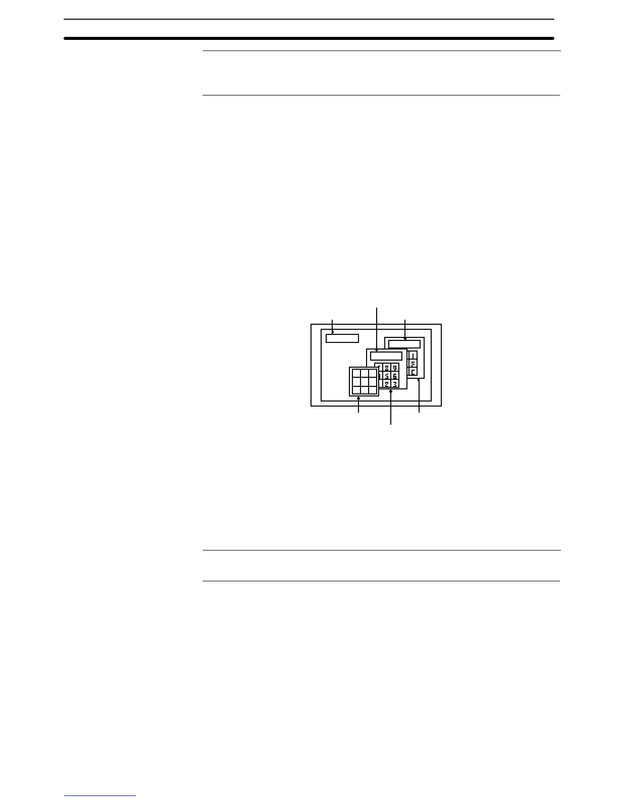
Example:
Character string
input field
Temporary input field 1
Temporary input field 2
AB C
DE F
GH I
Window 1
Window 3
Window 2
In the example above, window 2 is a focus window. All the input indicated below
is performed to a temporary input field on window 2.
• Input from a character string key on base screen
• Input from a character string key on window 1
• Input from a character string key on window 2
• Input from a character string key on window 3
• Input from a bar code reader
Reference: When a window 3 is touched on the position other than touch switch, the display
order of the windows is switched and the window 3 will be the focus window.