4-3SectionCommands/Responses
388
Response
Only if Yes is set for the Response memory switch, the response indicated below
is returned on normal completion.
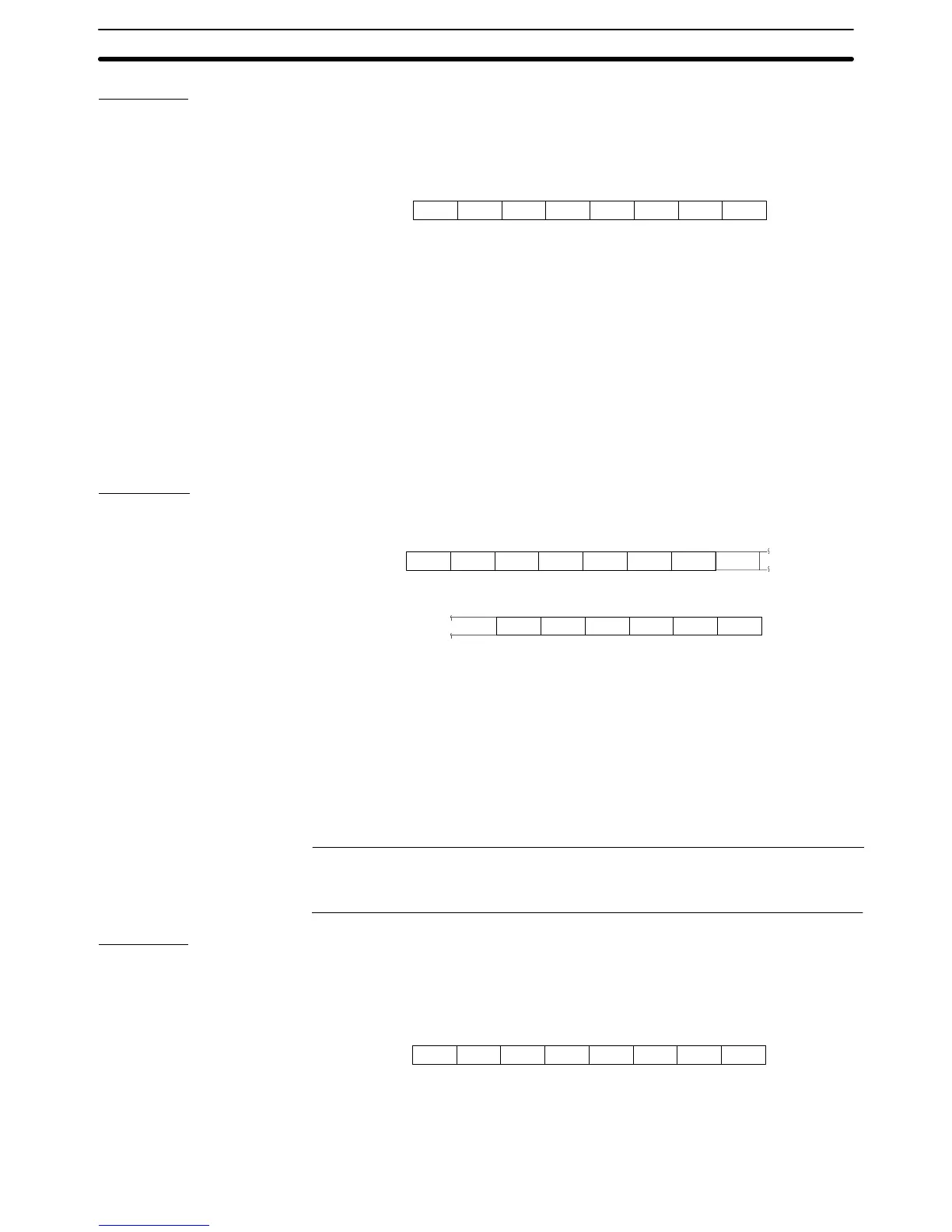
Format
1B 43
[ESC] [CR]C
3130 31 0D53
S
30
0 0 s1 s2
s
1
, s
2
: Checksum (2 hexadecimal digits)
This is always added (fixed as 11H).
Function
• Writes 40 characters of space code (20H) to all the character string memory
table entries within the specified range.
• If settings are omitted for both the first cleared character string memory table
entry number and the final cleared character string memory table entry num-
ber, all the character string memory table entries are cleared. It is not possible
to omit just one of these settings.
4-3-14 Bit Memory Table Clear Command (Sent from Host to PT)
Command
Format
m
1B 43
[ESC]
C
(e3)
(b3)
(e4)
42
B (b1) (b2)
0D
(b4)
(e1) (e2)
(s1) (s2) [CR]
* * * * * * * * * *
* * * * * * * * * * * *
m: Checksum present/absent (1 BCD digit)
0: Absent
1: Present
b
1
to b
4
: First cleared bit memory table entry number (4 BCD digits)
0000 to 0999
e
1
to e
4
: Final cleared bit memory table entry number (4 BCD digits)
0000 to 0999
s
1
, s
2
: Checksum (2 hexadecimal digits)
When m is 0, omit this setting.
Reference: The maximum number that can be specified for bit memory table entries de-
pends on the setting for numbers of bit memory table entries (256/1000) made at
the Support Tool.
Response
Only if Yes is set for the Response memory switch, the response indicated below
is returned on normal completion.
Format
1B 43
[ESC] [CR]C
3030 30 0D42
B
30
0 0 s1 s2
s
1
, s
2
: Checksum (2 hexadecimal digits)
This is always added (fixed as 00H).
Writes OFF (0) to all the bit memory table entries within the specified range.Function