Terminals
Wire type
Wire size
Conductor
length
(stripping
length)
Twisted wires Solid wire
Classification
Current ca-
pacity
Plated
Unplat-
ed
Plated
Unplat-
ed
All terminals ex-
cept ground ter-
minals
2 A max. Possi-
ble
Possible Possible Possible 0.08 to 1.5
mm
2
(A
WG 28 to
16)
8 to 10 mm
Greater than
2 A and 4 A
or less
Not pos-
sible
Possible
*1
Not pos-
sible
Ground termi-
nals
--- Possi-
ble
Possible
Possible Possible
2.0 mm
2
10 to 12 mm
*1. Secure wires to the screwless clamping terminal block. Refer to Securing Wires on page
5-47 for how
to secure wires.
Precautions for Correct Use
• Use cables with suitable wire sizes for the carrying current. There are also restrictions on the
current due to the ambient temperature. Refer to the manuals for the cables and use the ca-
bles correctly for the operating environment.
• For twisted wires, strip the sheath and twist the conductor portion. Do not unravel or bend the
conductor portion of twisted wires or solid wires.
Unravel wires Bend wires
NG NG
Additional Information
If more than 2 A will flow on the wires, use plated wires or use ferrules.
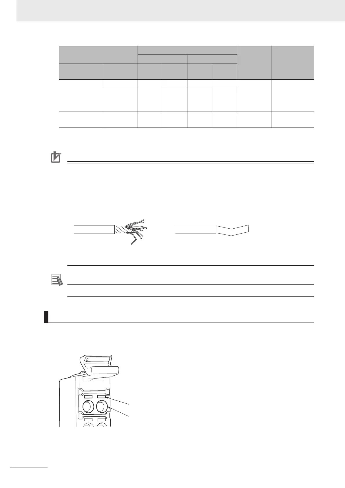
Connecting/Removing Wires
This section describes how to connect and remove wires.
l
Terminal Block Parts and Names
Terminal hole
Release hole
5 Installation and Wiring
5-44
NX-series NX502 CPU Unit Hardware User's Manual (W629)

 Loading...


