3 Configuration
3 - 72
Vision System FH/FZ5 series Hardware Setup Manual (Z366)
For operation at launch OSD, refer to the Model FH-MT12 INSTRUCTION SHEET.
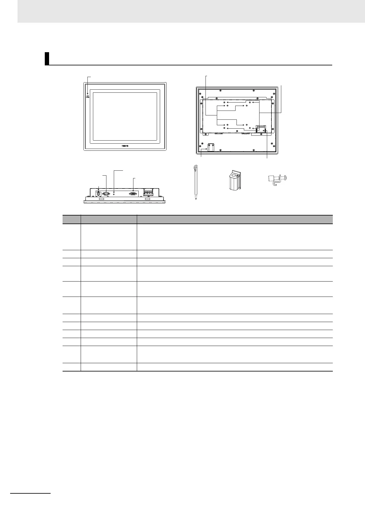
Component Names and Functions
Name Description
(1) LED indicator lamp Lit up green when power is ON.
Lit up orange when video signal is no input.
Unlit when power is OFF.
(2) VESA mounting hole Mounting hole for VESA 75 mm × 75
mm.
(3) VESA mounting hole Mounting hole for VESA 100 mm × 100 mm.
(4) USB retaining
br
acket
Retaining bracket for USB cable.
(5) Power supply termi-
nal
Connect a 24 VDC power supply.
(6) Monitor connector
(analog RGB)
Connect a monitor cable for analog RGB.
(7) OSD Menu button The button to activate the OSD menu.
(8) RS-232C Connect a serial communication port for touch panel communication.
(9) USB (TypeB) Connect a USB port (Type B) for touch panel communication.
(10) Touch pen Use for operation of touch panel.
(11) Touch pen holder Put touch pen in it when not using.
Paste it on the monitor by double-sided tape.
(12) Mounting Brackets Use them to mount the panel.
●Front view
(1) LED indicator lamp
●Rear view
(2) VESA mounting hole pitch 75 mm (M4)
(3) VESA mounting hole pitch 100 mm (M4)
(5) Power supply terminal
(4) USB retaining bracket
●Connection terminal
(6) Monitor connector
(analog RGB)
(9) USB (TypeB)
(8) RS-232C
(7) OSD Menu button
(10) Touch pen
(11) Touch pen holder
(12) Mounting Brackets

 Loading...

