5 - 23
5 Setup and Wiring
Vision System FH/FZ5 series Hardware Setup Manual (Z366)
5-3 Sensor Controller Installation
5
5-3-4 FZ5 Series
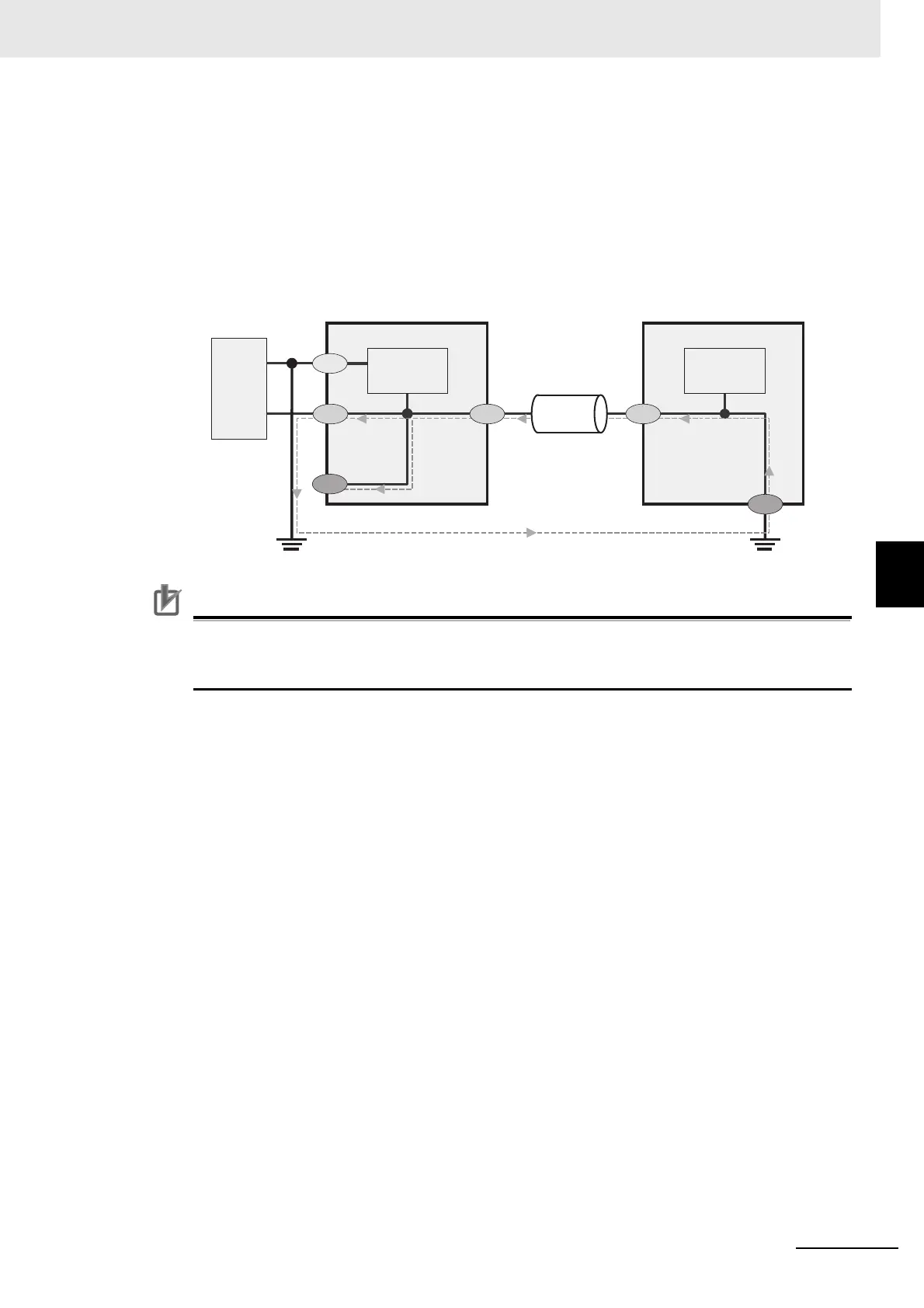
• Circuit ground (0 VDC) and frame ground are connected together. When connecting a
non-isolated device or a non-isolated interface to the controller, take appropriate actions to
avoid communication failures or damage to the mentioned ports.
• By the following case, make the connections so th
at the FG terminal of the connected device
has the same electrical potential as the controller. A difference in electrical potential between
the connected device and the controller may cause failure or malfunction.
• Ground the FG terminal of the non-isolated device
• Ground the SG (0 VDC) terminal of the isola
ted device or the non-isolated device
• Ground the SG (0 VDC) terminal of the controller
Precautions for Correct Use
The LCD panel used for the LCD-integrated type has been made using precision technology,
and sometimes a few pixels are missing in the panel. This is due to the structure of the LCD
panel, and is not a malfunction.
SG:
FG:
Signal Ground
Frame Ground
Non-isolated DeviceController
Non-isolated
Interface
Power
supply
circuit
Power
supply
circuit
Power
supply
FG
FG
SG
SGSG
24 V
 Loading...


