5 Setup and Wiring
5 - 24
Vision System FH/FZ5 series Hardware Setup Manual (Z366)
Use the cables and crimping terminals with the specified dimensions.
Keep the power supply wires as short as possible (Max.10 m).
Wire the power supply unit inde
pendently of other devices.
Do not directly connect an electric wire to t
he terminal block that is simply twisted.
Make sure that the controller is grounded with a separate ground wire.
After wiring, replace the terminal cover.
Power source types for FZ5 series differ depending
on the number of cameras due to current consump-
tion differences. Refer to the following table to use
the appropriate type. When you connect your cam-
era to the lighting via Light C
ontroller, the current consumption is same as when the Intelligent Compact
Digital camera is connected.
FZ5-1200 Series/FZ5-800 Series
FZ5-1100 Series/FZ5-600 Series
• Make sure to tighten all inst
allation screws securely.
• Maintain a minimum clearance of 50 mm above the con
troller to improve air circulation. Install the
FZ5 Sensor Controller with a clearance of 30 mm on the right, left side, and 10 mm for rear planes.
However, if the adjacent devices do not generate heat, provide at least 50 mm of clearance from the
top of the Controller. For the clearance at the bottom and sides, follow the mounting method.
• Do not install the product immediately above significan
t heat sources, such as heaters, transformers,
or large-capacity resistors.
• Do not let the ambient temperature exceed 50°C (122°F).
• Provide a forced-air fan cooling or air conditioning if the ambient temperature is near 50°C (122°F) so
tha
t the ambient temperature never exceeds 50°C (122°F).
• Do not install the product in a cabinet containing high-voltage equipment.
• Do not install the Sensor Controller within 200 mm of power cables.
Connection of Terminal Block of FZ5 Series
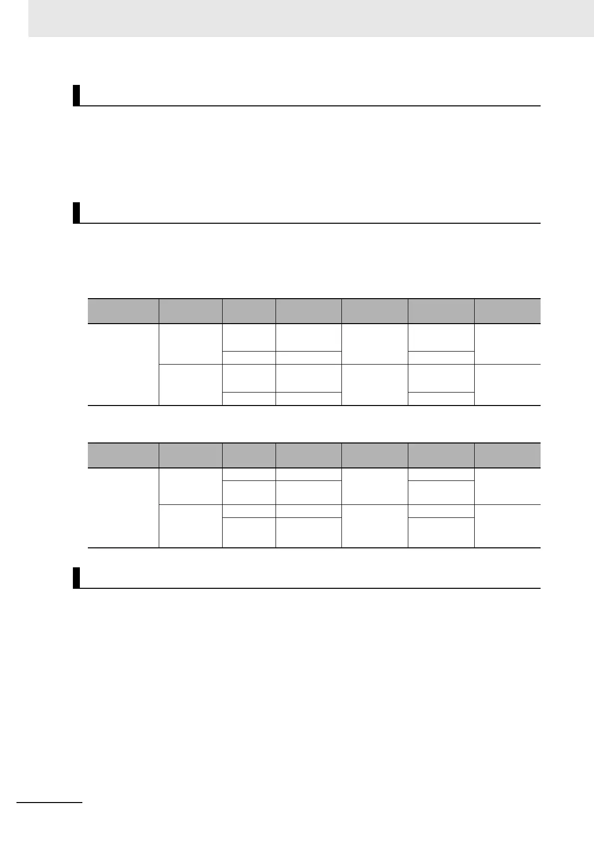
Recommended Power Source for FZ5 Series
Item
Camera
Type
Number of
Cameras
FZ5-80 FZ5-80-10 FZ5-120 FZ5-120-10
Recommended
Sour
ce
S8VK-G
S8VS
Intelligent
Compact Dig-
ital Camera
2
S8VK-G12024
S8VS-12024
S8VK-G24024
S8VS-18024
S8VK-G12024
S8VS-12024
S8VK-G24024
S8VS-18024
4 --- ---
0.3/2/5
meg
apixel
camera
2 S8VK-G12024
S8VS-09024
S8VK-G12024
S8VS-12024
S8VK-G12024
S8VS-09024
S8VK-G12024
S8VS-12024
4 --- ---
Item
Camera
Type
Number of
Cameras
FZ5-60 FZ5-60-10 FZ5-110 FZ5-110-10
Recommended
Sour
ce
S8VS
Intelligent
Compact Dig-
ital Camera
2 S8VS-12024 S8VS-18024 S8VS-12024 S8VS-18024
4 --- ---
0.3/2/5
meg
apixel
camera
2 S8VS-09024 S8VS-12024 S8VS-09024 S8VS-12024
4 --- ---
Mounting of the FZ5 Series

 Loading...

