6 I/O Interface
6 - 20
Vision System FH/FZ5 series Hardware Setup Manual (Z366)
Terminal assignments and signal names should be set according to the FH Sensor Controller's opera-
tion mode settings. Verify that the wiring conforms to that.
For Operation Mode, refer to the Setting the Operation Mode in Vision System FH/FZ5 Series
(Cat. No. Z365).
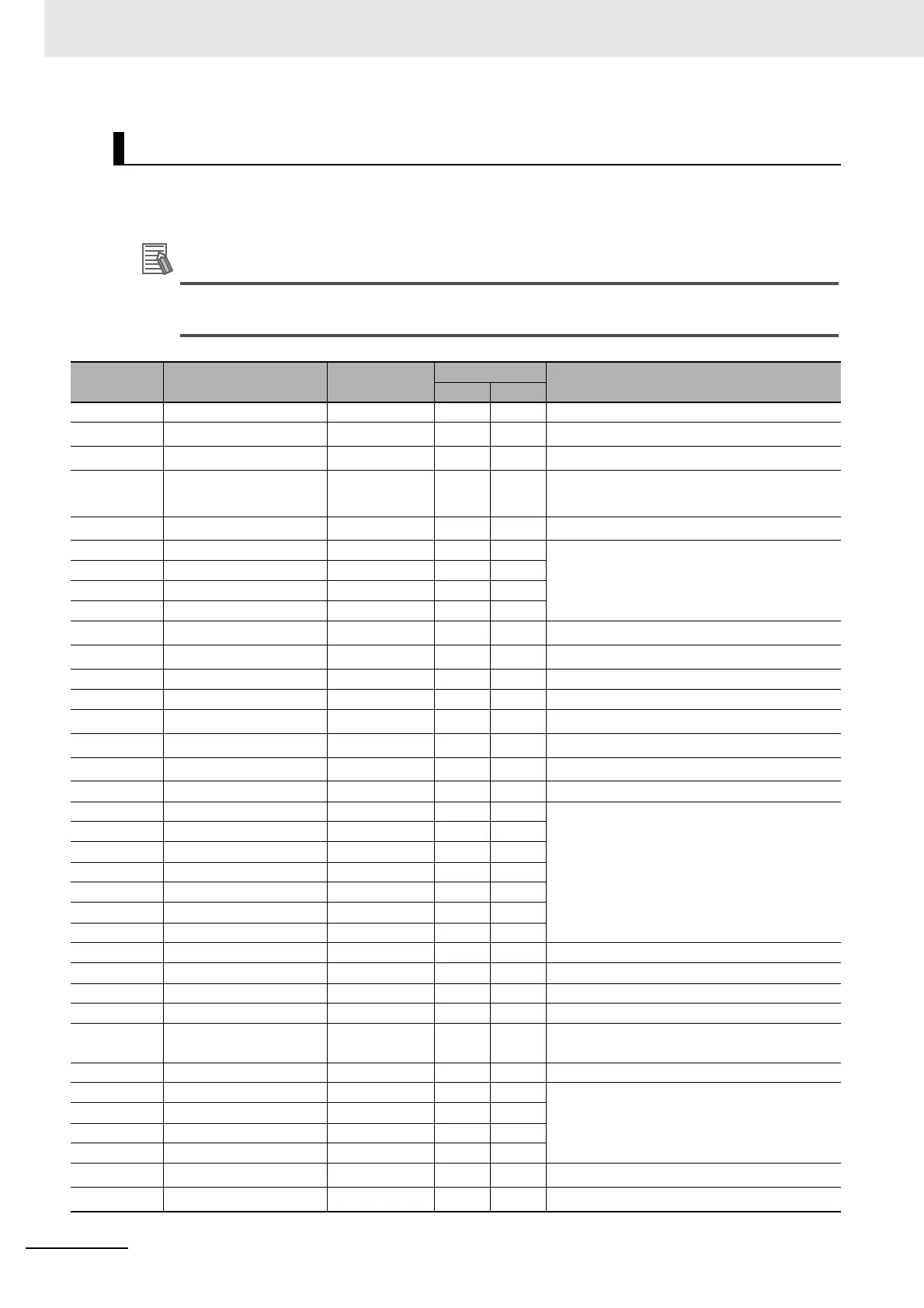
Pin Layout
No. Signal name Wire color
Mark
Function
Color Shape
A1 COMIN Orange Red ■ Common for input signals
A2
ENCTRIG_A1
*2
Gray Red ■ Encoder trigger input (Phase A)
A3
ENCTRIG_B1
*2
White Red ■ Encoder trigger input (Phase B)
A4
STEP1
*2
/
ENCTRIG_Z1
*2
Yellow Red ■ Measurement trigger input/
Encoder trigger input (Phase Z)
A5
DSA1
*2
Pink Red ■ Data send request signal
A6 DI1 Orange Red ■■ Command inputs
A7 DI3 Gray Red ■■
A8 DI5 White Red ■■
A9 DI7 Yellow Red ■■
A10 STGOUT1 Pink Red ■■
Strobe trigger output
*1
A11 STGOUT3 Orange Red ■■■
Strobe trigger output
*1
A12 ERROR Gray Red ■■■ ON when there is an error.
A13 COMOUT1 White Red ■■■ Common for output signals
A14
GATE1
*2
Yellow Red ■■■ ON for the set output time
A15
OR1
*2
Pink Red ■■■ Overall judgment result
A16
READY1
*2
Orange Red ■■■■ ON when image input is allowed
A17 COMOUT2 Gray Red ■■■■ Common for output signals
A18 DO1 White Red ■■■■ Data output
A19 DO3 Yellow Red ■■■■
A20 DO5 Pink Red ■■■■
A21 DO7 Orange
Red
■■■■■■■■■■■■■■■■■■■■■■■■■■■■■■■■■■■■■■■■
A22 DO9 Gray Red
■■■■■■■■■■■■■■■■■■■■■■■■■■■■■■■■■■■■■■■■
A23 DO11 White Red
■■■■■■■■■■■■■■■■■■■■■■■■■■■■■■■■■■■■■■■■
A24 DO13 Yellow Red
■■■■■■■■■■■■■■■■■■■■■■■■■■■■■■■■■■■■■■■■
A25 COMOUT3 Pink Red
■■■■■■■■■■■■■■■■■■■■■■■■■■■■■■■■■■■■■■■■
Common for output signals
B1 RESET Orange Black ■ Controller restart
B2 ENCTRIG_A0 Gray Black ■ Encoder trigger input (Phase A)
B3 ENCTRIG_B0 White Black ■ Encoder trigger input (Phase B)
B4 STEP0/ENCTRIG_Z0 Yellow Black ■ Measurement trigger input/
Encoder trigger input (Phase Z)
B5 DSA0 Pink Black ■ Data send request signal
B6 DI0 Orange Black ■■ Command inputs
B7 DI2 Gray Black ■■
B8 DI4 White Black ■■
B9 DI6 Yellow Black ■■
B10 STGOUT0 Pink Black ■■
Strobe trigger output
*1
B11 STGOUT2 Orange Black ■■■
Strobe trigger output
*1

 Loading...

