6 - 21
6 I/O Interface
Vision System FH/FZ5 series Hardware Setup Manual (Z366)
6-1 Parallel Interface
6
6-1-4 NPN Input/Output for FZ5 Series
• Handling the output common terminals
COMOUT1: STGOUT0 to 3, RUN/BUSY1,
ERROR, BUSY0, OR0 to 1, GATE0 to 1
COMOUT2: READY0 to 1, DO0 to 7
COMOUT3: DO8 to 15
*1. This is a signal that is used when the strobe device is connected to the Controller.
*2. This signal is only available in the Random trigger mode.
*3. ON while the layout turned on output setting is displayed/ON during processing
a) [Input]
Applicable signals/
RESET, DI0 to DI7, DSA0, DSA1
b) [Input]
Applicable signals/
STEP0/ENCTRIG_Z0, STEP1/ENCT
RIG_Z1, ENCTRIG_A0 to 1, ENCTRIG_B0 to 1
B12
RUN/BUSY1
*2
Gray Black ■■■
*3
B13 BUSY0 White Black ■■■ ON during processing
B14 GATE0 Yellow Black ■■■ ON for the set output time
B15 OR0 Pink Black ■■■ Overall judgment result
B16 READY0 Orange Black ■■■■ ON when image input is allowed
B17 DO0 Gray Black ■■■■ Data output
B18 DO2 White Black ■■■■
B19 DO4 Yellow Black ■■■■
B20 DO6 Pink Black ■■■■
B21 DO8 Orange Black
■■■■■■■■■■■■■■■■■■■■■■■■■■■■■■■■■■■■■■■■
B22 DO10 Gray Black
■■■■■■■■■■■■■■■■■■■■■■■■■■■■■■■■■■■■■■■■
B23 DO12 White Black
■■■■■■■■■■■■■■■■■■■■■■■■■■■■■■■■■■■■■■■■
B24 DO14 Yellow Black
■■■■■■■■■■■■■■■■■■■■■■■■■■■■■■■■■■■■■■■■
B25 DO15 Pink Black
■■■■■■■■■■■■■■■■■■■■■■■■■■■■■■■■■■■■■■■■
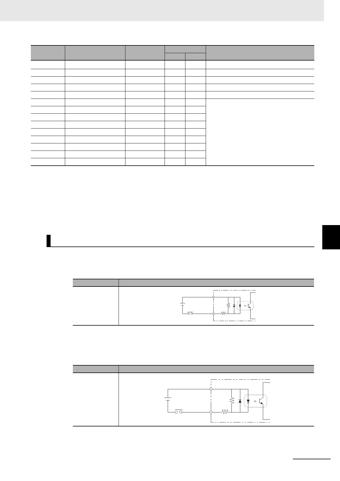
Internal Specifications for Parallel Interface
Item Specifications
Internal circuit
diagram
Item Specifications
Internal circuit
di
agram
No. Signal name Wire color
Mark
Function
Color Shape
Each input terminal
COM IN
+
Each input terminal
COM IN
+

 Loading...

