3 - 21
3 Configuration
Vision System FH/FZ5 series Hardware Setup Manual (Z366)
3-1 Sensor Controller
3
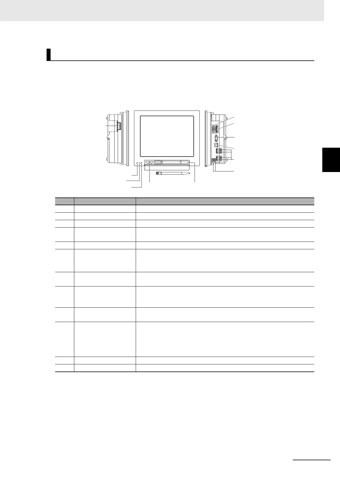
3-1-3 FZ5-600/FZ5-800/FZ5-1100/FZ5-1200 Series
Component Names and Functions
Connector name Description
(1) POWER LED Lit while power is ON.
(2) RUN LED Lit while the layout turned on output setting is displayed.
(3) ERROR LED Lit when an error has occurred.
(4) I/O connector (control
lin
es, data lines)
Connect the controller to external devices such as a sync sensor.
(5) Camera connector Connect cameras.
(6) Power and Ground ter-
minal
Connect a DC power supply.
Wire the power supply unit independently of other devices.
After wiring, replace the terminal cover.
(7) Power and Ground ter-
minal
Connect the ground wire. Make sure tha
t the controller is grounded with a
separate ground wire.
(8) Monitor connector (ana-
log RGB)
For FZ5-600/FZ5-1100 series, cannot connect the monitor.
For use this connector, contact OMRON representative.
FZ5-800 Series/FZ5-1200 Series: Connect monitor.
(9) RS-232C/RS-422 con-
nector
Connect an external device such as a personal computer or PLC.
(10) USB connector Connect a USB device. Do not plug or unplug it during measurement.
Measurement time might be affected otherwise. However, when connecting
two or mo
re USB memories, do not connect them to adjacent ports. Doing so
may
cause the USB memories to come into contact, resulting in malfunction
or damage.
(11) Ethernet connector Connect Ethernet device.
(12) Touch pen (holder) A touch pen is stored.
(6)(7)Power and
Ground terminal
(1)POWER LED
(2)RUN LED
(3)ERROR LED
(10)USB connector (12)Touch pen (holder)
(9)RS-232C/RS-422 connector
(4)I/O connector
(control lines, data lines)
(8)Monitor connector
(analog RGB)
(11)Ethernet connector
(5)Camera connector
(10)USB connector
Left-side view Right-side viewFront view
Camera 2ch type
FZ5-120
FZ5-110
FZ5-80
FZ5-60
Camera 4ch type
FZ5-120-10
FZ5-110-10
FZ5-80-10
FZ5-60-10

 Loading...

