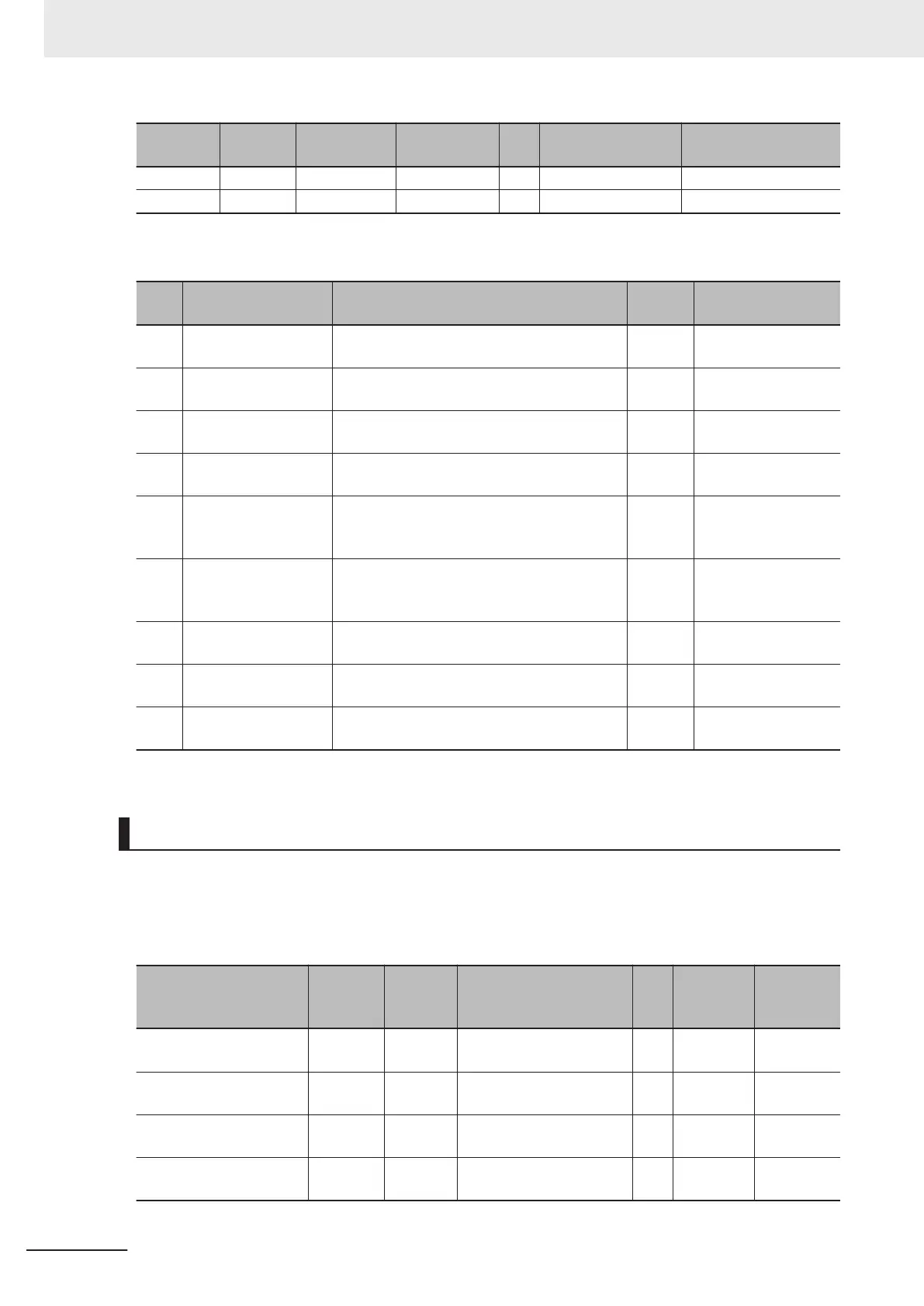
Data name Data type Default value I/O port name Unit Index number (hex)
Subindex number
(hex)
Ch3 Status WORD 0000 hex Ch3 Status --- 6003 01
Ch4 Status WORD 0000 hex Ch4 Status --- 6004 01
The bit configuration and the description of each bit for the Ch£ Status are given in the following ta-
ble.
Bit Data name
Description
*1
Data
type
I/O port name
0
Ch£ Disconnection
Detection Status
1: A disconnection was detected.
0: A disconnection was not detected.
BOOL
Ch£ Disconnection
Detection Status
1
Ch£ Under Range
1: An under range was detected.
0: An under range was not detected.
BOOL
Ch£ Under Range
2
Ch£ Over Range
1: An over range was detected.
0: An over range was not detected.
BOOL
Ch£ Over Range
3
Ch£ Digital Low-
pass Filter Disabled
1: The digital low-pass filter is disabled.
0: The digital low-pass filter is enabled.
BOOL
Ch£ Digital Low-
pass Filter Disabled
4
Ch£ Moving A
verage
Filter 1 Disabled
1: The moving average filter 1 is disabled. Or
it has not reached the average count.
0: The moving average filter 1 is enabled.
BOOL
Ch£
Moving Aver-
age Filter 1 Disabled
5
Ch£ Moving Average
Filter 2 Disabled
1: The moving average filter 2 is disabled. Or
it has not reached the average count.
0: The moving average filter 2 is enabled.
BOOL
Ch£
Moving Aver-
age Filter 2 Disabled
6
Ch£ Zero Set Exe-
cuting
1: The zero set is in progress.
0: The zero set is not in progress.
BOOL
Ch£ Zero Set Exe-
cuting
7
Ch£ T
rigger Input
1: The trigger input is ON.
0: The trigger input is OFF.
BOOL
Ch
£
Trigger Input
8 to
15
Ch£
Reserved
--- --- ---
*1. 1 is TRUE and 0 is FALSE.
Ch£ Trigger Input Time Stamp
This indicates the DC time at which the trigger input changes from OFF to ON during the NX bus I/O
refresh cycle. If the trigger input changes from OFF to ON more than once during the cycle, the DC
time at the first change is recorded. Refer to 8-10 Trigger Input
on page 8 - 40 for details on the appli-
cations of this data and the timing when it is obtained.
Data name Data type
Default
value
I/O port name Unit
Index
number
(hex)
Subindex
number
(hex)
Ch1 Trigger Input Time
Stamp
ULINT 0 Ch1 Trigger Input Time
Stamp
ns 6001 02
Ch2 Trigger Input Time
Stamp
ULINT 0 Ch2 Trigger Input Time
Stamp
ns 6002 02
Ch3 Trigger Input Time
Stamp
ULINT 0 Ch3 Trigger Input Time
Stamp
ns 6003 02
Ch4 Trigger Input Time
Stamp
ULINT 0 Ch4 Trigger Input Time
Stamp
ns 6004 02
The bit configuration of the Ch£ Trigger Input Time Stamp (ULINT) is given in the following table.
7 I/O Data and List of Settings
7 - 8
NX-series Analog I/O Units User’s Manual for High-speed Analog Input Units (W592)