EasyManua.ls Logo

Omron SYSMAC NX series User Manual

Omron SYSMAC NX series
306 pages
To Next Page IconTo Next Page
To Previous Page IconTo Previous Page
Page #152 background image
Connection made to Screen
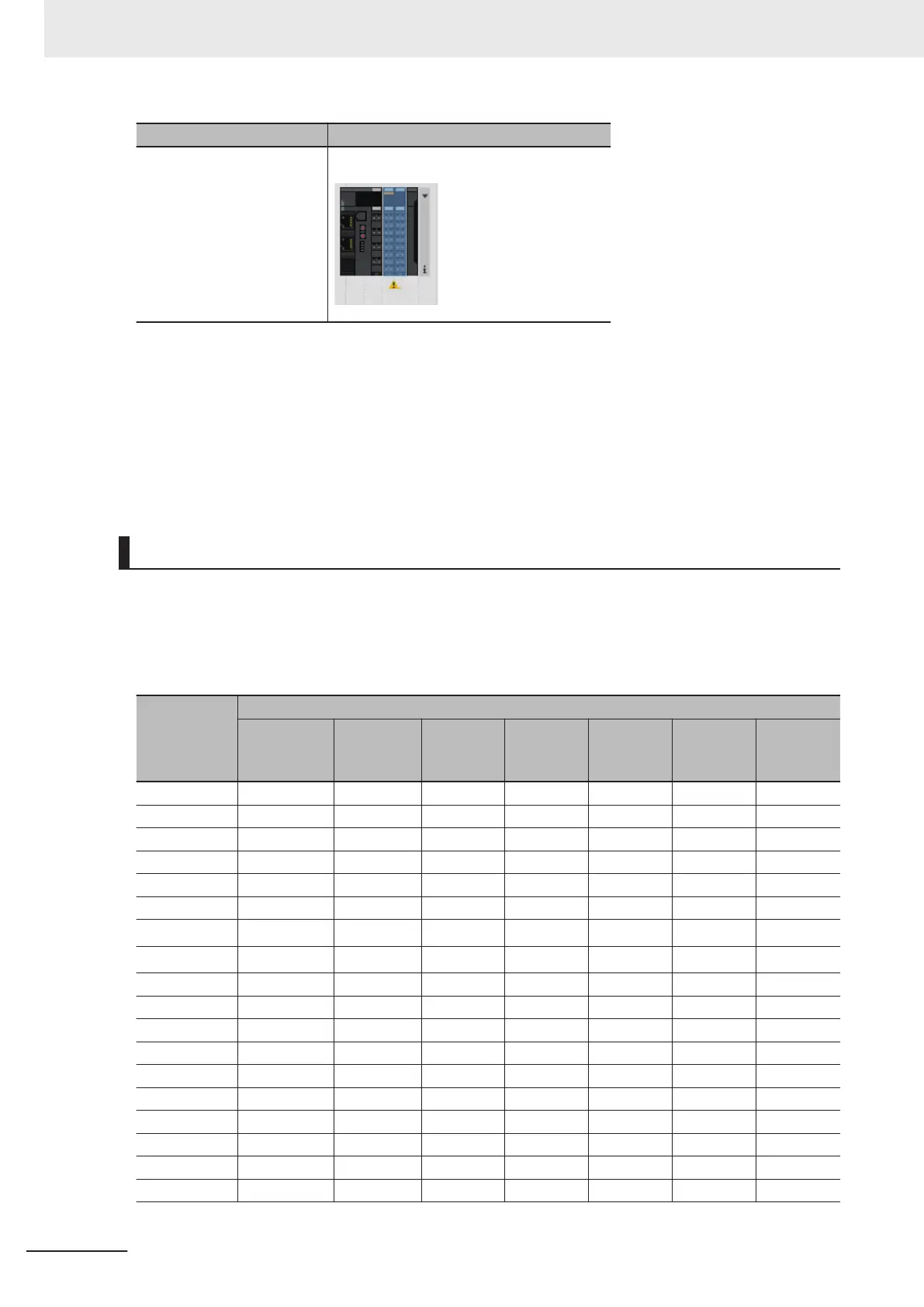
Communication Coupler Unit Edit Slave Terminal Configuration Tab Page
After completion of the settings, check with the Support Software that the following conditions are met:
The limitations on the I/O data size are not exceeded.
*1
No I/O Refreshing T
imeout Error occurred.
*2
*1. If you connect to the CPU Unit, check this on the CPU and Expansion Racks Tab Page. If you connect to the
Communications Coupler Unit, check this on the Edit Slave Terminal Configuration Tab Page.
*2.
Check this on the Multi-view Explorer.
Examples of Possible Sampling Period Settings
The following table shows examples of sampling periods that you can set. The task periods shown be-
low are typical values. Refer to the user’s manual for the connected CPU Unit for information on possi-
ble task period values.
If the sampling period is indicated as "---", it is less than 5 µs and you cannot set I/O allocations.
Number of
samplings
[times]
Sampling period [µs]
Task period
125 µs
*1
Task peri-
od 250 µs
Task peri-
od 500 µs
Task peri-
od 1000
µs
Task peri-
od 2000
µs
Task peri-
od 4000
µs
Task peri-
od 8000
µs
1 125 250 500 1000 2000 4000 8000
2 62.5 125 250 500 1000 2000 4000
4 31.25 62.5 125 250 500 1000 2000
5 25 50 100 200 400 800 1600
8 15.625 31.25 62.5 125 250 500 1000
10 12.5 25 50 100 200 400 800
20
6.25
*2
12.5 25 50 100 200 400
25
5
*2
10 20 40 80 160 320
40 --- 6.25 12.5 25 50 100 200
50 --- 5 10 20 40 80 160
80 --- --- 6.25 12.5 25 50 100
100 --- --- 5 10 20 40 80
125 --- --- --- 8 16 32 64
200 --- --- --- 5 10 20 40
250 --- --- --- --- 8 16 32
400 --- --- --- --- 5 10 20
500 --- --- --- --- --- 8 16
625 --- --- --- --- --- 6.4 12.8
8 Functions
8 - 10
NX-series Analog I/O Units Users Manual for High-speed Analog Input Units (W592)

Table of Contents

Other manuals for Omron SYSMAC NX series

Question and Answer IconNeed help?

Do you have a question about the Omron SYSMAC NX series and is the answer not in the manual?

Omron SYSMAC NX series Specifications

General IconGeneral
I/O CapacityUp to 2560 I/O points
Communication PortsRS-232C
Communication ProtocolsEtherNet/IP
Operating Temperature0°C to 55°C
Programming LanguagesFunction Block Diagram, Sequential Function Chart
EtherNet/IP Ports1 or 2
Built-in USB Port1
Humidity10% to 90% (non-condensing)
Vibration Resistance10 to 57 Hz, 0.075 mm amplitude
Built-in RS-232C PortOptional
Storage Temperature-25°C to 65°C
Shock Resistance147m/s², 3 times in each direction (X, Y, Z)

Summary

Section 1 Features and System Configuration

Section 2 Specifications and Operating Procedures

Section 3 Part Names and Functions

Section 4 Installation and Wiring

Section 5 I/O Refreshing

Safety Precautions

Warnings

Provides critical warnings regarding power supply handling, fail-safe measures, and voltage/current inputs.

Precautions for Safe Use

Installation

Details safety precautions for installing the Unit, including power supply status and avoiding contact with connector pins.

Wiring

Provides safety precautions for wiring, including double-checking settings, using correct parts, and handling cables.

Power Supply Design

Outlines precautions for power supply design, including voltage ranges, current capacity, and external breakers.

Using the High-speed Analog Input Unit

Highlights precautions for using the High-speed Analog Input Unit, including orientation and placement restrictions.

Precautions for Correct Use

Storage, Mounting, and Wiring

Provides precautions for storage, mounting, and wiring, warning against improper locations and static discharge.

Regulations and Standards

1 Features and System Configuration

1-1 Features

Provides an overview of the key features of the NX-series High-speed Analog Input Units.

1-2 System Configuration

Explains system configurations for connecting NX Units to CPU Units or Communications Coupler Units.

1-4 List of Functions

Describes the various functions supported by the High-speed Analog Input Units.

2 Specifications and Operating Procedures

2-1 Specifications

Details the general and individual specifications for the High-speed Analog Input Units.

2-2 Operating Procedures

Outlines the overall procedure and detailed steps for configuring the unit and creating user programs.

3 Part Names and Functions

3-1 Part Names

Identifies and describes the names and functions of the physical parts of the High-speed Analog Input Units.

4 Installation and Wiring

4-1 Installing NX Units

Details restrictions on installation, including orientation and adjacent unit placement for NX Units.

4-2 Power Supply Types and Wiring

Explains the two types of power supplies for NX Units and their wiring methods.

4-3 Wiring the Terminals

Describes how to wire the terminals, including screwless clamping blocks and wire preparation.

4-4 Wiring External Devices

Provides information on wiring the High-speed Analog Input Units to external devices, including examples.

5 I/O Refreshing

5-1 I/O Refreshing

Describes I/O refreshing between CPU Units and NX Units, and between PCs/CPU Units and Slave Terminals.

6 Input Range and Converted Values

6-1 Voltage Input Range and Converted Values

Details the voltage input ranges and how analog voltage signals are converted to digital values.

6-2 Current Input Range and Converted Values

Details the current input ranges and how analog current signals are converted to digital values.

7 I/O Data and List of Settings

7-2 Setting I/O Allocations with the Sysmac Studio

Explains how to configure I/O allocation settings using Sysmac Studio, covering display and setup.

8 Functions

8-4 Number of Samplings Setting

Describes how to set the number of samplings per period to determine the sampling period.

8-5 Digital Filtering

Explains the use of digital filters (low-pass, moving average) to suppress noise and stabilize measurements.

8-8 User Calibration

Describes the function for correcting offsets in converted values due to unit deterioration and calibrating the units.

8-10 Trigger Input

Details how to obtain digital input signal values that trigger analog input signals and the DC time of changes.

9 Troubleshooting

9-3 Checking for Errors and Troubleshooting on the Support Software

Details how to check errors using Sysmac Studio, including current errors, logs, and event codes.

9-5 Unit-specific Troubleshooting

Provides a table of common problems, their assumed causes, and corrections specific to the High-speed Analog Input Units.

10 Inspection and Maintenance

Related product manuals