• Task period of assigned periodic task: 1 ms
• Number of Ch1 samplings: 5
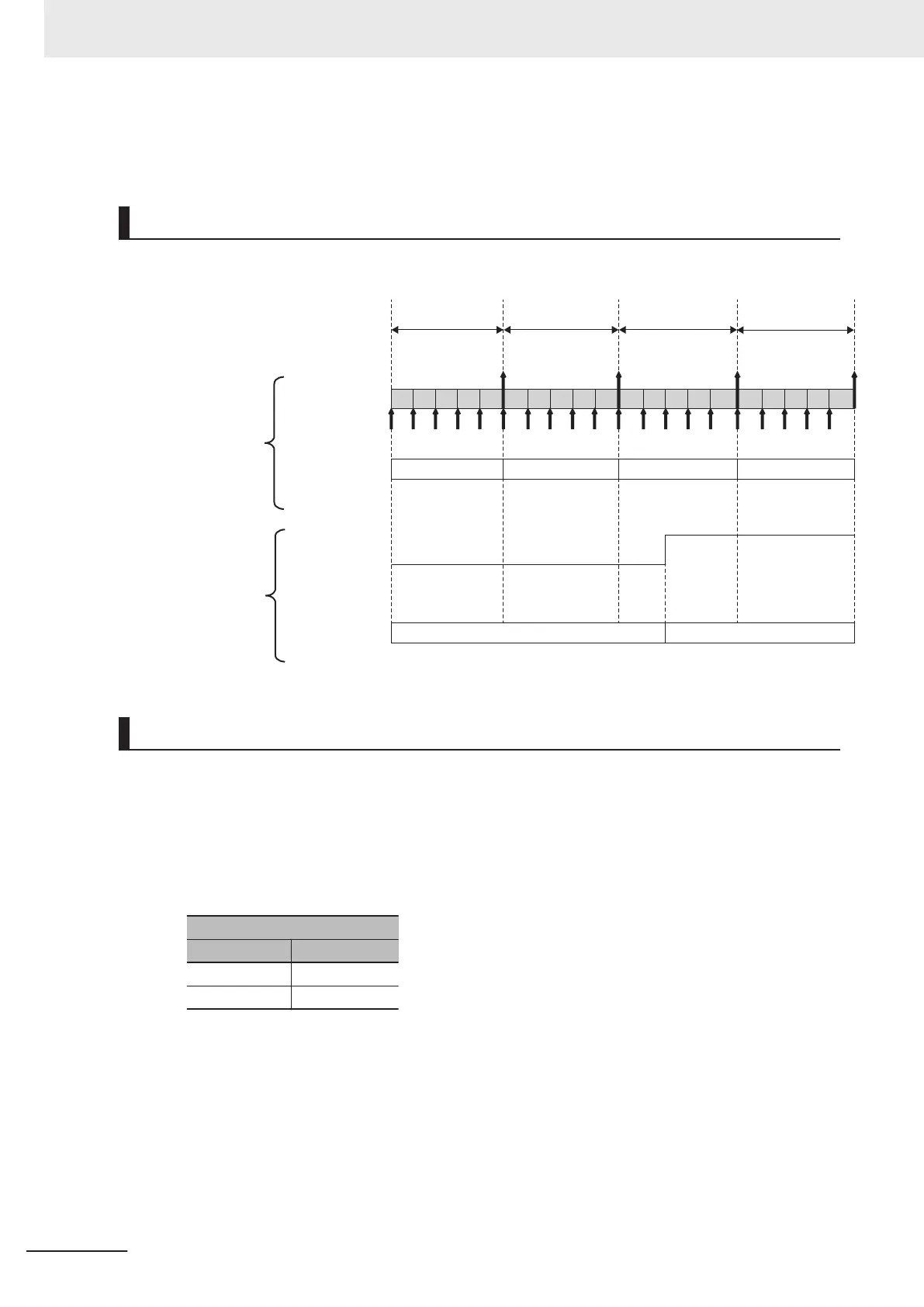
Timing Chart Example
The following figure shows the timing chart.
1
Tana0: 0 ms Tana1: 1 ms Tana2: 2 ms
2 3 4 5 1
2
3 4 5
1 2 3 4 5
Analog input to the
High-speed Analog
Input Unit
Ch1: Number of
Samplings set
to 5
Analog input
Time Stamp
1 ms
Tana3: 3 ms
1 2 3 4 5
Ttrg0: 0 ms
Ttrg1: 2.4 ms
Trigger input to the
High-speed Analog
Input Unit
Ch1 Trigger
Input
Ch1 Trigger Input
Time Stamp
Identification Method
The identification method is described below.
1 Check the DC time of the Ch1 Trigger Input Time Stamp when the Ch1 trigger input was turned
ON.
The Ch1 Trigger Input Time Stamps in the above timing chart example are shown in the follow-
ing table.
Ch1 Trigger Input Time Stamp
Symbol DC time
Ttrg0 0 ms
Ttrg1 2.4 ms
The Ch1 Trigger Input Time Stamp when the Ch1 trigger input was turned ON is Ttrg1, and the
DC time of Ttrg1 is 2.4 ms.
You can check the Trigger Input T
ime Stamp with the Ch£ Trigger Input Time Stamp of I/O
data. Refer to Ch
£
Trigger Input Time Stamp on page 7 - 8 for details on I/O data. The unit of
the Ch£ Trigger Input Time Stamp of I/O data is ns.
2 Check the DC time of the Analog Input Time Stamp immediately before Ttrg1.
The Analog Input T
ime Stamps in the above timing chart example are shown in the following
table.
8 Functions
8 - 46
NX-series Analog I/O Units User’s Manual for High-speed Analog Input Units (W592)