Dimensions 24 (W) × 100 (H) × 71 (D) Isolation method Between the analog input and the
NX bus: Power = Transformer,
Signal = Digital isolator
Between analog inputs: Power =
T
ransformer, Signal = Digital isola-
tor
Between the trigger input and the
NX bus: Signal = Digital isolator
Between the analog input and the
trigger input: Power = Transform-
er, Signal = Digital isolator
Insulation resistance 20 MΩ min. between isolated cir-
cuits (at 100 VDC)
Dielectric strength 510 VAC between isolated circuits
for 1 minute at a leakage current
of 5 mA max.
I/O power supply
method
Supply from the NX Bus Current capacity of
I/O power supply ter-
minals
IOV: 0.1 A max. per terminal
IOG: 0.1 A max. per terminal
NX Unit power con-
sumption
• Connected to a CPU Unit
3.30 W max.
• Connected to a Communica-
tions Coupler Unit
2.95 W max.
Current consumption
from I/O power sup-
ply
30 mA max.
Weight 140 g max.
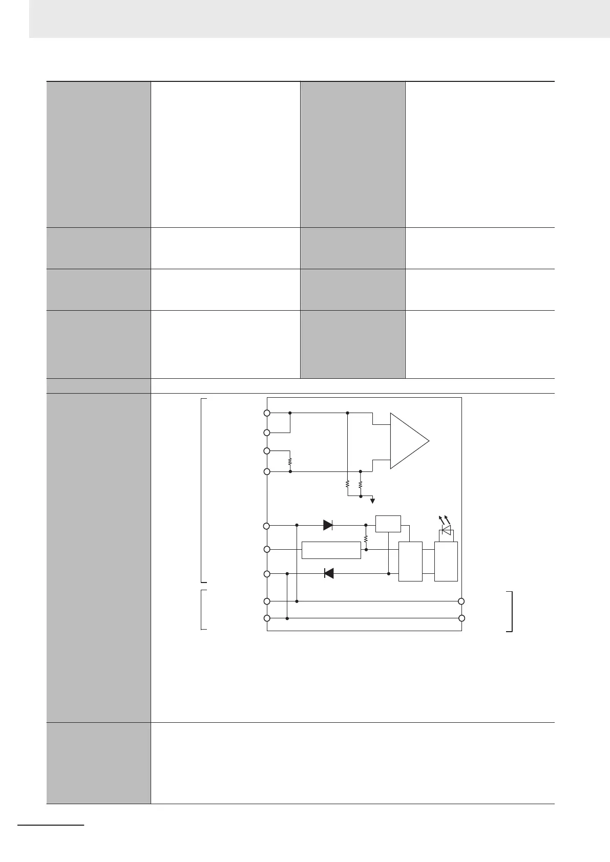
Circuit Configuration
250 Ω
510 kΩ
510 kΩ
AG1 to 4
Isolation
circuit
Internal
circuits
I/O power
supply +
I/O power
supply -
Input1+ to 4+
Terminal
block
NX bus
connec-
tor (left)
SHT1+ to 4+
SHT1- to 4-
IOV1 to 4
IN1 to 4
IOG1 to 4
Input1- to 4-
Current
control circuit
Power
supply
I/O power
supply +
NX bus
connector
(right)
I/O power
supply -
The following channels are individually isolated.
• Input1+, Input1-, SHT1+, SHT1-
• Input2+, Input2-, SHT2+, SHT2-
• Input3+, Input3-, SHT3+, SHT3-
• Input4+, Input4-, SHT4+, SHT4-
Installation orienta-
tion and restrictions
*2
Installation orientation:
• Connected to a CPU Unit
Possible in upright installation.
• Connected to a Communications Coupler Unit
Possible in upright installation.
Restrictions: No restrictions
Appendices
A - 6
NX-series Analog I/O Units User’s Manual for High-speed Analog Input Units (W592)