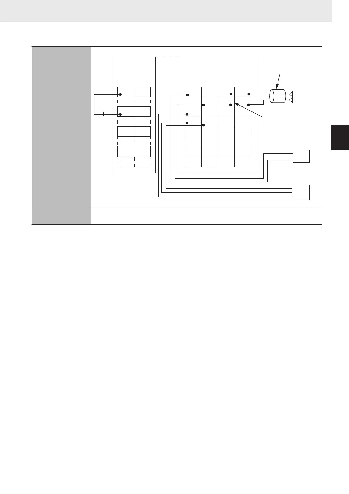
Terminal connection
diagram
24 VDC
A1 B1
A8 B8
IOV
IOG
IOV
IOG
IOV
IOG
IOV
IOG
A1 B1 C1 D1
A8 B8 C8 D8
IN1
IN2
IN3
IN4
NC
NC
NC
NC
SHT1+
SHT2+
SHT3+
SHT4+
Input1+
Input2+
IOV2 IOG2 SHT2- Input2-
IOV1 IOG1 SHT1- Input1-
Input3+
IOV3 IOG3 SHT3- Input3-
Input4+
IOV4 IOG4 SHT4- Input4-
Additional I/O Power
Supply Unit
*3
Use a two-conductor
shielded twisted-pair
cable. Do not ground
the shield.
To use current input,
connect SHT□+ and
SHT□- with a
short-circuit cable.
*4
High-speed Analog Input Unit
NX-HAD401
Two-wire sensor
Three-wire sensor
Output device
Input+
Input-
Input disconnection
detection
*5
• When the input range is 1 to 5 V or 4 to 20 mA: Supported
• Other input range: Not supported
*1. This is the minimum value. The Units perform conversion in the sampling period determined based on the Number of
Samplings Setting. The sampling period must be set to this value or longer.
*2. The following Unit cannot be connected next to the Unit.
• Relay Output Unit (NX-OC
££££)
*3. Besides the Additional I/O Power Supply Unit, there are Units that can supply I/O power to the NX bus. For example,
you can use a Connected Communications Coupler Unit. If you use this Unit to supply I/O power to the High-speed
Analog Input Units, the Additional I/O Power Supply Unit is unnecessary. The Additional I/O Power Supply Unit is also
unnecessary if you do not use the trigger inputs of the High-speed Analog Input Units.
*4. Short-circuit cables are not included in the product. The cable length must be 4 cm or less and allow for wiring to the
screwless clamping terminal block. Be sure to use cables and ferrules that are applicable to the screwless clamping
terminal block.
If the cable is too long, the analog input values may not be accurate.
*5.
To use this function, set the Disconnection Detection Enable/Disable to Enable.
Appendices
A - 7
NX-series Analog I/O Units User’s Manual for High-speed Analog Input Units (W592)
A-1 Data Sheet
A
A-1-2 High-speed Analog Input Units