FUEL
PUMP
TEST
PUMP
ASSEMBLY
I
Test the fuel pump by checking the pump outlet pres-
sure. Use the following procedure.
1.
Remove the fuel line from the pump outlet and
install a pressure gauge.
2. Press the START switch and hold it for several
seconds until pressure reading is constant.
3. Pressure reading should be 2-112 to 3-1/4 psi
(17.2 to 22.4 kPa). If the retension is good,
the
pressure should stay constant or drop
off
very
slowly.
A
low pressure reading with little or no pressure drop
indicates a weak or broken diaphragm or diaphragm
spring, worn linkage or leaky check valves. If pres-
sure is above maximum, the pump diaphragm
is
too
tight or the diaphragm (or plunger) return spring
is
too strong. Any of the above conditions are cause for
repair or replacement
of
the pump.
ELECTRIC FUEL
PUMP
The Facet and Bendix pumps incorporate a hollow
stainless steel plunger in a brass cylinder. The plunger
has no gland or seal, but is freely fitted. The fluid
being pumped provides the seal by filling the small
clearance between the plunger and cylinder. Energiz-
ing the pump's electric solenoid pulls the plunger
downward, compressing the return spring. When the
solenoid is de-energized, the return spring drives the
plunger back, delivering fuel to the pump outlet.
DO
not substitute automotive type
electric fuel pumps for sfandard
Onan supplied electric pumps. The output pressure
is much higher and can cause carburetor flooding or
fuel leakage, creating a fire hazard.
Fuel
Pump
Repair
Service of the Facet pump is limited to the bottom
cover, filter, plunger tube, and plunger assembly.
All
parts
of
the electric system are hermetically sealed
in
a gas atmosphere and are not serviceable. If electrical
failure occurs, replace the pump.
Do not tamper with the seal at the
Lzz2
center of the mounting bracket on
the side of the pump as it retains the dry gas which
surrounds the electrical system. Electrical system
components are not serviceable.
Use the following procedure for servicing the pump:
1.
Using a5/8-inch wrench, loosen, the pump cover,
2.
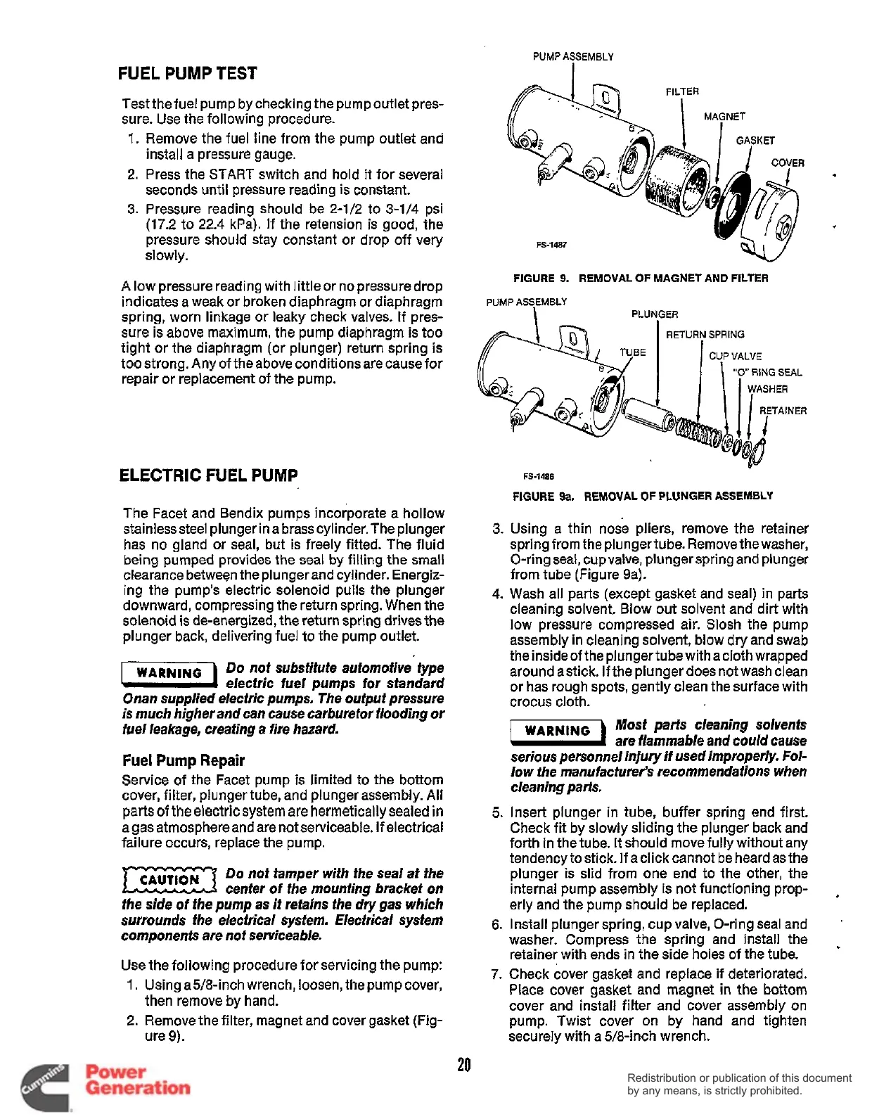
Remove
the
filter, magnet and cover gasket (Fig-
then remove by hand.
ure 9).
81
a]
1
1
GASKET
%
1
COVER
FS-1487
FIGURE
9.
REMOVAL
OF
MAGNET AND
FILTER
PUMP
ASSEMBLY
PLUNGER
"0"
RING
SEAL
WASHER
3.
4.
5.
6.
7.
FS-1486
FIGURE
9a.
REMOVAL
OF
PLUNGER ASSEMBLY
Using a thin nose pliers, remove the retainer
spring from the plungertube. Removethewasher,
O-ring seal, cup valve, plunger spring and plunger
from tube (Figure sa).
Wash all parts (except gasket and seal) in parts
cleaning solvent, Blow out solvent and dirt with
low pressure compressed air. Slosh the pump
assembly in cleaning solvent, blow dry and swab
the inside of the plungertube with a cloth wrapped
around astick. If the plunger does not wash clean
or has rough spots, gently clean the surface with
crocus cloth.
Most parts cleaning solvents
are flammable
and
could cause
serious personnel injury if used improperly. Fol-
low the manufacturer's recommendations when
cleaning parts.
Insert plunger in tube, buffer spring end first.
Check fit by slowly sliding the plunger back and
forth in the tube.
It
should move fully without any
tendency tostick. If aclick cannot be heard as the
plunger
is
slid from one end
to
the other, the
internal pump assembly is not functioning prop-
erly and the pump should be replaced.
Install plunger spring, cup valve, O-ring seal and
washer. Compress the spring and install the
retainer with ends in the side holes of the tube.
Check cover gasket and replace if deteriorated.
Place cover gasket and magnet in the bottom
cover and install filter and cover assembly on
pump. Twist cover on by hand and tighten
securely with a 5/8-inch wrench.
20
Redistribution or publication of this document
by any means, is strictly prohibited.
Redistribution or publication of this document
by any means, is strictly prohibited.
 Loading...


