Engine
Disasse.mbly
If
engine disassembly is necessary, first remove all
the. complete assemblies (e.g. manifold with car-
buretor and vacuum speed booster). Individual
assemblies, as the carburetor, can be removed and
serviced later, if necessary. Follow the general dis-
assembly steps given below and refer to the ap-
propriate detailed instructions in this section. When
reassembling; check the text for special assembly
instructions.
Keep
alt
parts
in
their respective order
.
.
.
valve
assemblies,. rod caps for respective rod and piston
assemblies, etc. Analyze reasons for parts failures.
Use new gaskets for assembly.
GENERAL
DISASSEMBLY
1.
2.
3.
4.
5.
6.
7.
8.
9.
t
0.
11.
12.
1
3.
4
6.
Install crank gear aligning timing mark with mark
7.
Install valve assemblies and cylinder heads.
8.
Install gear cover and
oil
seal.
9.
Install flywheel.
10.
Install fuel pump, manifold assembly, air cleaner,
..
fuel lines, spark plug, breaker box, etc.
11.
Connect electrical wires, exhaust line and
battery.
12. Fill crankcase with proper oil.
on camshaft gear.
1
.
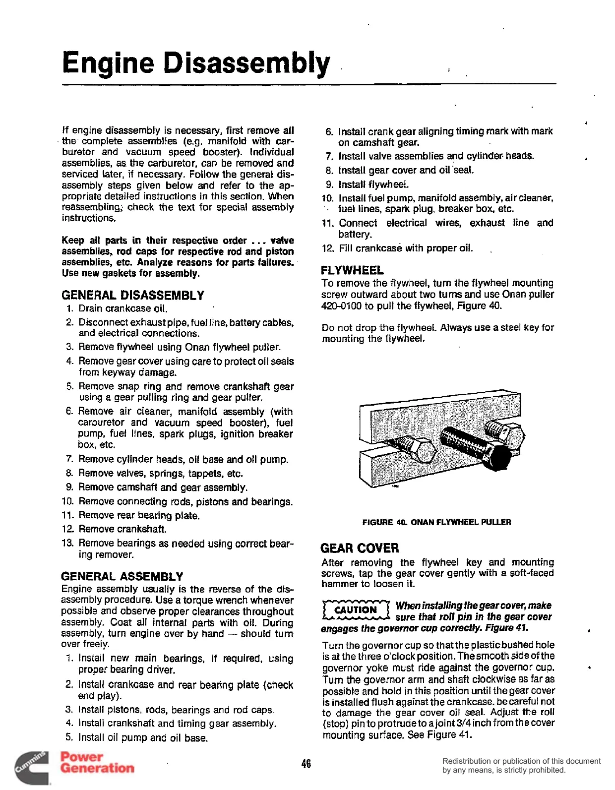
FLYWHEEL
To
remove the flywheel, turn the flywheel mounting
screw outward about two turns and use Onan puller
~~
-
Drain crankcase oil.
420-0100 to pull the flywheel, Figure
40.
Disconnect exhaust
pipe7fuelline,
Do
not drop the flywheel. Always use astee1 key for
mounting the flywheel.
and electrical connections.
Remove flywheel using Onan flywheel puller.
Remove gear cover using care to protect oil seals
from keyway damage.
Remove snap ring and remove crankshaft gear
using
a
gear pulling ring and gear pulter.
Remove air cleaner, manifold assembly (with
carburetor and vacuum speed booster), fuel
pump, fuel lines, spark plugs, ignition breaker
box, etc.
Remove cylinder heads, oil base and oil pump.
Remove valves, springs, tappets, etc.
Remove camshaft and gear assembly.
Remove connecting rods, pistons and bearings.
Remove rear bearing plate.
Remove crankshaft.
FIGURE
40.
ONAN
FLYWHEEL
PULLER
Remove bearings as needed using correct bear-
ing remover.
GEAR
COVER
After removing the flywheel key and mounting
GENERAL
ASSEMBLY
Engine assembly usually is the reverse of the dis-
assembly procedure. Use a torque wrench whenever
possible and observe proper clearances throughout
assembly. Coat all internal parts with oil. During
assembly, turn engine over by hand
-
should turn
over freely.
1.
Install new main bearings, if required, using
2.
Install crankcase and rear bearing plate (check
3.
Install pistons, rods, bearings and rod caps.
4.
Install crankshaft and timing gear assembly.
5.
Install oil pump and oil base.
proper bearing driver.
end play).
screws, tap the gear cover gently with a soft-faced
hammer to loosen
it.
When
installing the gear cover, make
E3
sure
that
roll
pin
in
fhe
gear
cover
engages fhe governor
cup
correctly. Figure
41.
Turn the governor cup
so
that the plastic bushed hole
is at the three o’clock position. Thesmooth side of the
governor yoke must ride against the governor cup.
Turn the governor arm and shaft clockwise as far
as
possible and hold in this position until thegear cover
is installed flush against
the
crankcase. becareful not
to damage the gear cover oil seal. Adjust the roll
(stop) pin to protrude to ajoint
3/4
inch from the cover
mounting surface. See Figure
41.
b
.(
46
Redistribution or publication of this document
by any means, is strictly prohibited.
Redistribution or publication of this document
by any means, is strictly prohibited.
 Loading...


