CYLINDER
WALL
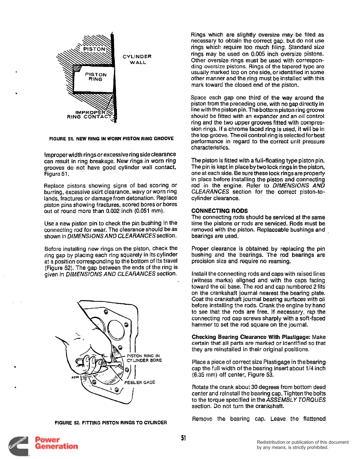
FIGURE
51.
NEW
RING
IN
WORN PISTON RING GROOVE
Improper width rings or excessive ring side clearance
can result
in
ring breakage. New rings
in
worn ring
grooves do not have good cylinder wall contact,
Figure
51.
Replace pistons showing signs
of
bad scoring or
burring, excessive skirt clearance, wavy or worn ring
lands, fractures or damage from detonation. Replace
piston pins showing fractures, scored bores or bores
out
of
round more than
0.002
inch
(0.051
mm).
Use a new piston pin to check the pin bushing in the
connecting rod for wear. The clearance should
be
as
shown in DIMENSIONS AND CLEARANCESsection.
Rings which are slightly oversize may be filed as
necessary to obtain the correct gap, but do not use
rings which require too much filing. Standard size
rings may be used on
0.005
inch oversize pistons.
Other oversize rings must be used with correspon-
ding
oversize pistons. Rings of the tapered type are
usually marked top
on
one side, or identified
in
some
other manner and the ring must be installed with this
mark toward the closed end of the piston.
Space each gap one third of the way around the
piston from the preceding one, with no gap directly
in
line with the piston pin. The bottom piston ring groove
should
be
fitted with an expander and an
oil
control
ring and the two upper grooves fitted with compres-
sion rings. If a chrome faced ring is used, it will be
in
the top groove. Theoil control ring is selected for best
performance in regard to the correct unit pressure
characteristics.
The piston
is
fitted with a full-floating type piston pin.
The pin is kept in place by two lock rings
in
the piston,
one at each side. Be sure these lock rings are properly
in place before installing the piston and connecting
rod
in
the engine. Refer to
DIMENSIONS
AND
CLEARANCES section for the correct piston-to-
cylinder clearance.
CONNECTING
RODS
The connecting rods should be serviced at the same
time the pistons orrods are serviced. Rods must be
removed
with
the piston. Replaceable bushings and
.
bearings are used.
Before installing new rings on the piston, check the
ring gap
by
placing each ring squarely in its cylinder
at
a
position corresponding to the bottom of its travel
(Figure
52).
The gap between the ends of the ring is
given in DlMENSlONS AND CLEARANCES section.
.
Proper clearance is obtained by replacing the
pin
bushing and the bearings. The rod bearings are
precision size and require no reaming.
Install the connecting rods and caps with raised lines
(witness marks) aligned and with
the
caps facing
toward the oil base. The rod and cap numbered
2
fits
on the crankshaft journal nearest the bearing plate.
Coat the crankshaft journal bearing surfaces with oil
before installing the rods. Crank the engine by hand
to see that the rods are free. If necessary, rap the
connecting rod cap screws sharply with a soft-faced
hammer to set the rod square on the journal.
Checking Bearing Clearance
With
Plastigage: Make
certain that all parts are marked or identified
so
that
they are reinstalled in their original positions.
Place a piece of correct size Plastigage in the bearing
cap the full width
of
the bearing insert about
1/4
inch
(6.35
mm) off center, Figure
53.
Rotate the crank about
30
degrees from bottom dead
center and reinstall the bearing cap.Tighten the bolts
to the torque specified
in
the ASSEMBLY
TORQUES
section.
Do
not turn the crankshaft.
PISTON
.RING
IN
CY
LlNDER BORE
FEELERGAGE
FIGURE
52.
FITTING
PISTON
RINGS
TO
CYLINDER
Remove the bearing cap. Leave the flattened
51
Redistribution or publication of this document
by any means, is strictly prohibited.
Redistribution or publication of this document
by any means, is strictly prohibited.
 Loading...


