CY
Ll
NDER
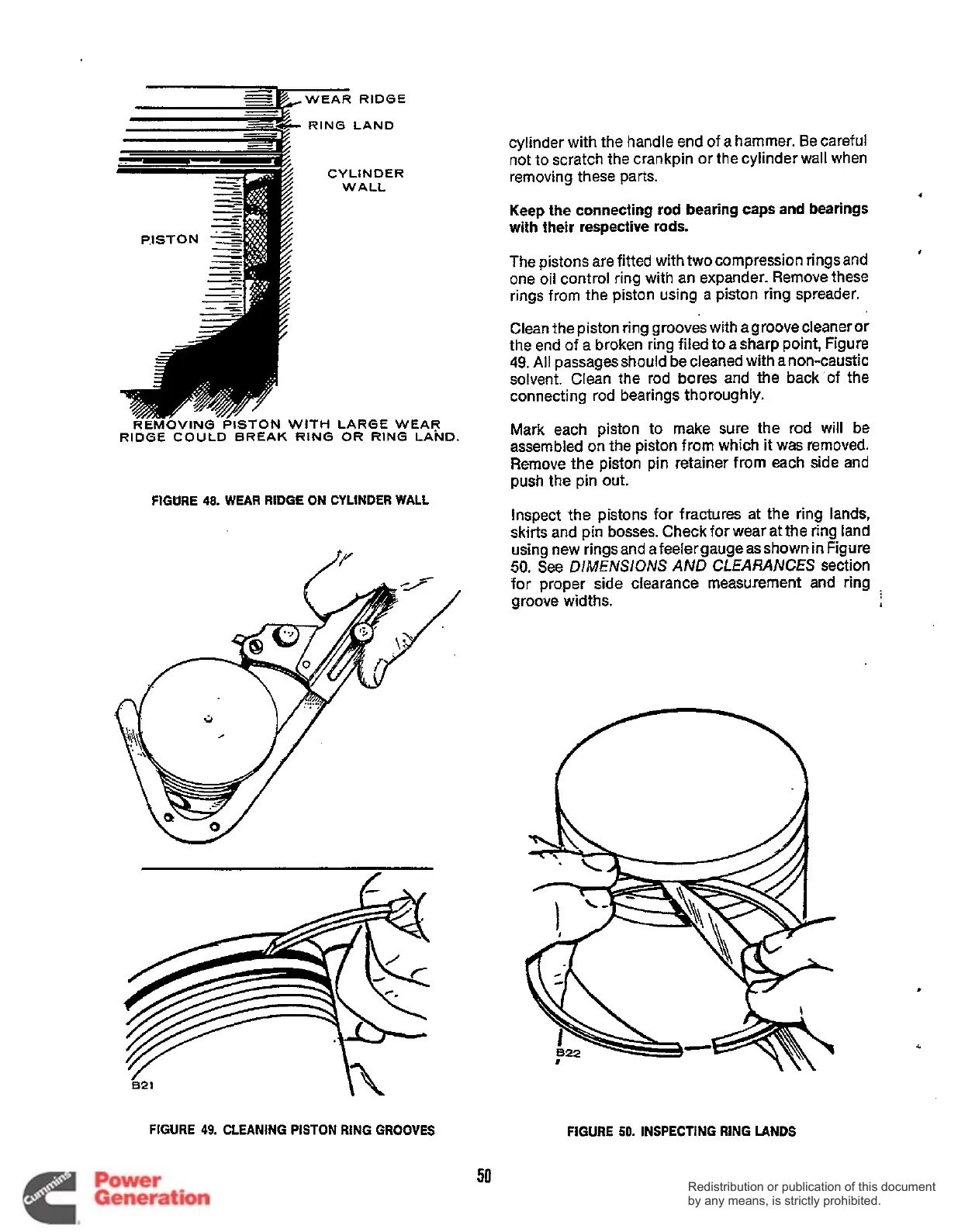
REMOVING PISTON
WITH
LARGE WEAR
RIDGE COULD BREAK RING
OR
RING LAND.
FIGURE
48.
WEAR RIDGE
ON
CYLINDER WALL
FIGURE
49.
CLEANING PISTON RING
GROOVES
cylinder with the handle end
of
a
hammer. Be careful
not to scratch the crankpin or
the
cylinder wall when
removing these parts.
Keep the connecting rod bearing caps and bearings
with their respective
rods.
The pistons
are
fitted with two compression rings and
one
oil
control ring with an expander. Remove these
rings from
the
piston using
a
piston ring spreader.
Clean
the
piston ring grooves with agroove cleaner or
the end
of
a
broken ring
filed
to asharp point, Figure
49.
All
passages should
be
cleaned with
a
non-caustic
solvent. Clean the rod bores and the
back
of
the
connecting rod bearings thoroughly.
Mark
each
piston to make sure the rod will
be
assembled on the piston from which it was removed.
Remove the piston pin retainer from each side and
push the pin out.
Inspect
the
pistons
for
fractures
at
the ring lands,
skirts and pin
bosses.
Check for wear at the ring land
using new rings and
a
feeler
gauge
as
shown in Figure
50.
See
DlAdENSlONS
AND
CLEARANCES
section
for
proper
side
clearance measurement and ring
.
groove widths.
1
4
#
FIGURE
50.
INSPECTING
RING
LANDS
50
Redistribution or publication of this document
by any means, is strictly prohibited.
Redistribution or publication of this document
by any means, is strictly prohibited.
 Loading...


