AMBIENT
TEMP.
(OF)
60
65
70
75
80
85
90
CHOKE
OPENING
864
95
100
LOOSEN
THIS
SCRW
AND
ROTATE
THE
ENTIRE COVER
-
YI
GZ-
-G
ASSEMBLY
CHOKE
OPENING
(Inches)
1/8
9/64
5/32
11/64
3/16 r3/64 7/32
15/64
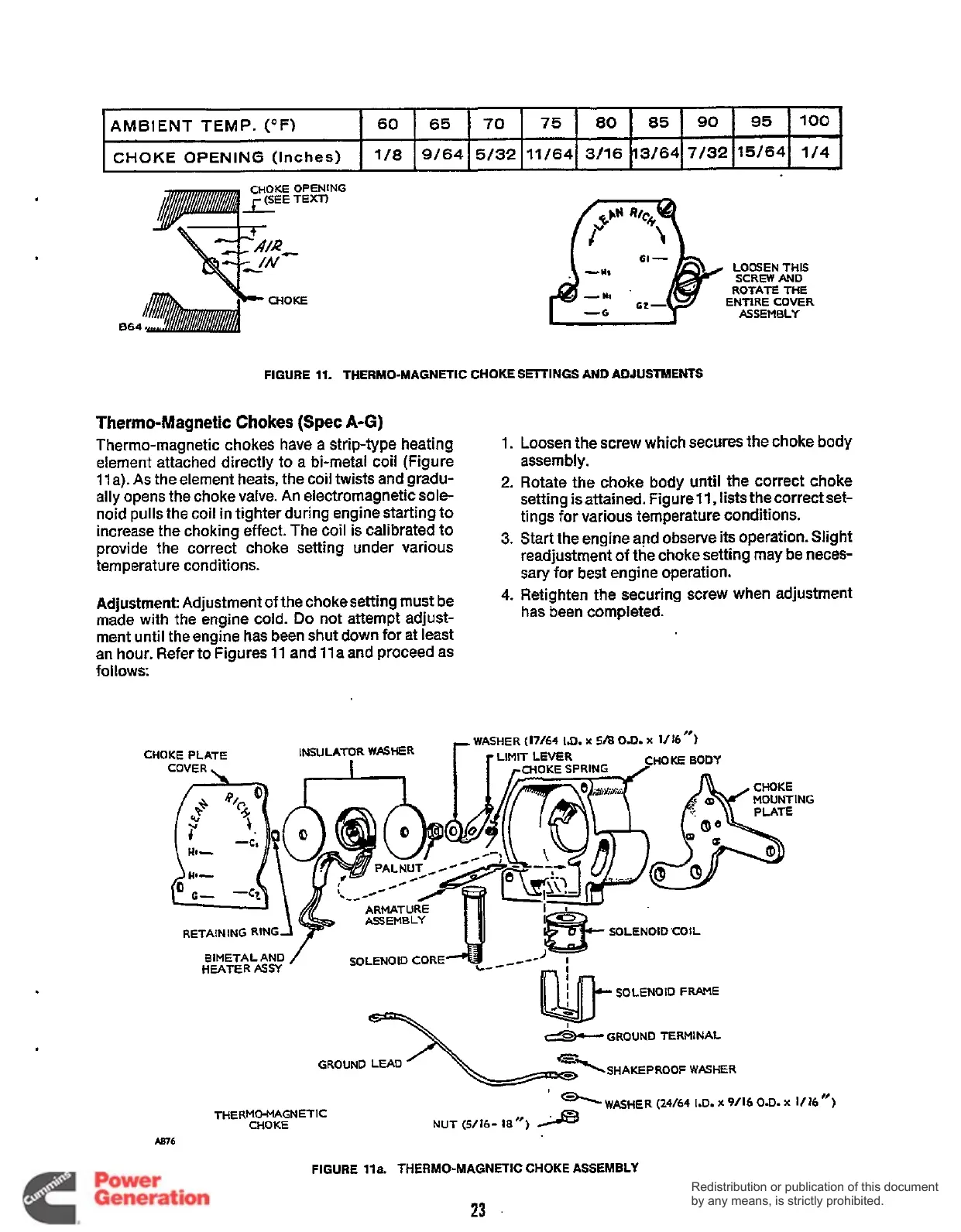
FIGURE
11.
THERMO-MAGNETIC CHOKE
SETTINGS
AND
ADJUSTMENTS
1/4
Thermo-Magnetic Chokes (Spec
A-G)
Thermo-magnetic chokes have a strip-type heating
element attached directly to a bi-metal coil (Figure
11
a). As the element heats, the coil twists and gradu-
ally opens the choke valve. An electromagnetic sole-
noid pulls the coil
in
tighter during engine starting to
increase the choking effect. The coil is calibrated to
provide the correct choke setting under various
temperature conditions.
1.
Loosen the screw which secures the choke body
assern bly.
2.
Rotate the choke body until the correct choke
setting is attained. Figure
11,
lists the correct set-
tings for various temperature conditions.
3.
Start the engine and observe its operation. Slight
readjustment
of
the choke setting may be neces-
sary for best engine operation.
Adjustment Adjustment of the choke setting must be
4-
Retighten the securing screw when adjustment
made with the engine
cold.
Do
not attempt adjust-
ment until the engine has been shut down for at least
an hour. Refer to Figures
11
and
11
a and proceed as
follows:
has
been completed.
‘
-WASHER
(24/64
I.D.
x
9/16
O.D.
x
1/16
”)
NUT
(5/16-
18”)
>
THERMO-MAGNETIC
CHOKE
A876
FIGURE
lla.
THERMO-MAGNETIC
CHOKE ASSEMBLY
23
Redistribution or publication of this document
by any means, is strictly prohibited.
Redistribution or publication of this document
by any means, is strictly prohibited.
 Loading...


