MCCK
Cooling
System
DESCR
I
PTI
0
N
The MCCK cooling system is a pressure type system
which uses an engine mounted rubber impeller pump
to draw and circulate raw water throughout the
system.
In open type cooling systems, water enters the pump
located on the front right side of engine. The pump
delivers water to the cylinder jacket. Water flows
through the jacket and out openings in cylinder
heads controlled by thermostats.' For engine warm-
up, with thermostats closed, a by-pass from the
cylinder block to the thermostat allows water flow.
From thermostat, water passes through the water-
cooled exhaust manifold and out engine cooling
system.
MAINTENANCE
Cooling system maintenance includes periodic in-
spection for leaks, inspection of the rubber pump
impeller, and flushing and cleaning.
Confacf
wifh
hof
coolanf
mighf
result
n
in serious burns.
Do
not bleed
hot,
pressurized coolant from
a
closed cooling sysfem.
The rubber impeller, because of continuous flexing,
will, in time, need replacement. If impeller fails after
short service (usually under'500 hours), check for
possible defects, such as severe pitting or abrasion
caused by dirt in
the
cooling system.
Cooling system MUST be kept clean to function
properly. Scale reduces heat transfer and restricts
water flow. Flush system at least once a year and
more often if operation indicates clogged passages,
pump wear, or overheating.
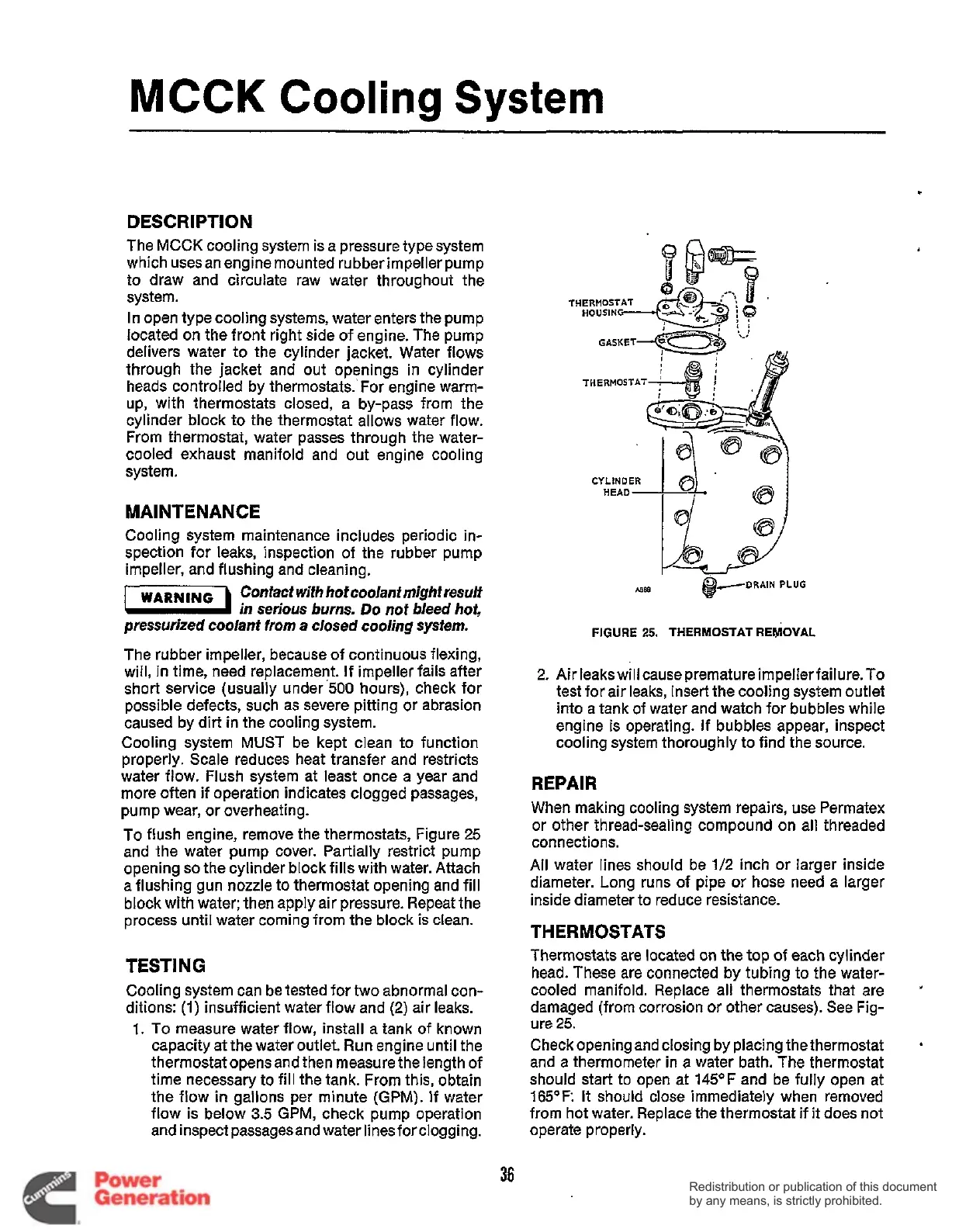
To flush engine, remove the thermostats, Figure
25
and the water pump cover. Partially restrict pump
opening
so
the cylinder block fills with water. Attach
a flushing gun nozzle to thermostat opening and fill
block with water; then apply air pressure. Repeat the
process until water coming from the block is clean.
WARNING
TESTING
Cooling system can be tested for two abnormal con-
ditions:
(1)
insufficient water flow and
(2)
air leaks.
1.
To
measure water flow, install a tank of known
capacity at the water outlet. Run engine until the
thermostat opens and then measure the length of
time necessary to fill the tank. From this, obtain
the flow
in
gallons per minute
(GPM).
If water
flow is below
3.5
GPM, check pump operation
and inspect passages and water linesforclogging.
THERMOSTAT
As888
@-DRAIN
PLUG
FIGURE
25.
THERMOSTAT
REMOVAL
2.
Air leaks will cause premature impeller failure.To
test for air leaks, insert the cooling system outlet
into a tank of water and watch for bubbles while
engine is operating. If bubbles appear, inspect
cooling system thoroughly to find the source.
REPAIR
When making cooling system repairs, use Permatex
or other thread-sealing compound on all threaded
connections.
All
water lines should be
1/2
inch or larger inside
diameter. Long runs of pipe or hose need a larger
inside diameter to reduce resistance.
THERMOSTATS
Thermostats are located on the
top
of each cylinder
head. These are connected by tubing to the water-
cooled manifold. Replace all thermostats that are
damaged (from corrosion or other causes). See Fig-
ure
25.
Check opening and closing by placing thethermostat
and a thermometer in a water bath. The thermostat
should start
to
open at
145OF
and be fully open at
165OF:
It should close immediately when removed
from hot water. Replace the thermostat if
it
does not
operate properly.
"
.
36
Redistribution or publication of this document
by any means, is strictly prohibited.
Redistribution or publication of this document
by any means, is strictly prohibited.
 Loading...


