Dimensions and Clearances
.
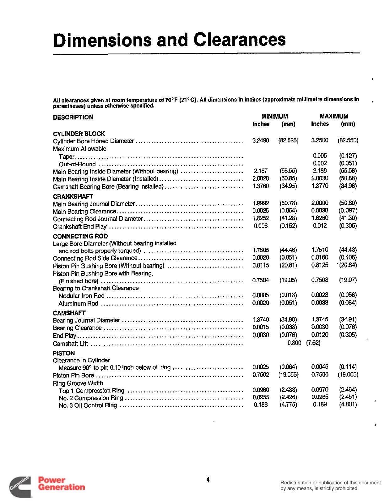
All
clearances given at
room
temperature
of
70°F
(21°C)
.
All
dimensions in inches (approximate millitnetre dimensions in
parentheses) unless otherwise specified
.
.
DESCRIPTION
CYLINDER BLOCK
Maximum Allowable
Cylinder Bore Honed Diameter
.........................................
Taper
................................................................
Out-of-Round
.......................................................
Main Bearing Inside Diameter (Without bearing)
........................
Main Bearing Inside Diameter (Installed)
................................
Camshaft Bearing Bore (Bearing installed)
..............................
CRANKSHAFT
Main Bearing Journal Diameter
.........................................
Main Bearing Clearance
................................................
Connecting Rod Journal Diameter
......................................
Crankshaft End Play
...................................................
CONNECTING
ROD
Large Bore Diameter (Without bearing installed
and rod bolts properly torqued)
......................................
Connecting Rod Side Clearance
........................................
Piston Pin Bushing Bore (Without bearing)
.............................
(Finished bore)
......................................................
Nodular Iron
Rod
....................................................
Aluminum Rod
......................................................
Bearing Journal Diameter
..............................................
Bearing Clearance
.....................................................
End Play
...............................................................
Camshaft Lift
..........................................................
PISTON
Clearance in Cylinder
Piston Pin Bore
........................................................
Ring
Groove
Width
Piston Pin Bushing Bore with Bearing.
Bearing to Crankshaft Clearance
CAMSHAFT
Measure
90"
to pin
0.10
inch below oil ring
...........................
Top
1
Compression Ring
............................................
No
.
2
Compression Ring
.............................................
No
.
3
Oil Control Ring
...............................................
Inches
3.2490
2.1 87
2.0020
1.3760
1.9992
0.0025
1.6252
0.006
1.7505
0.0020
0.81
15
0.7504
0.0005
0.0020
1.3740
0.001
5
0.0030
0.0025
0.7502
0.0960
0.0955
0.188
(mm)
Inches
(mm)
(82.525) 3.2500 (82.550)
0.005
(0.1 27)
0.002 (0.051)
(55.55)
2.188 (55.58)
(50.85) 2.0030 (50.88)
(34.95) 1.3770 (34.98)
(50.78) 2.0000 (50.80)
(0.064)
0.0038 (0.097)
(41.28) 1.6260 (41.30)
(0.1 52)
0.01
2
(0.305)
(44.46)
1.7510
(44.48)
(0.051) 0.0160
(0.406)
(20.61) 0.8125
*
(20.64)
(19.05)
0.7508 (19.07)
(0.013) 0.0023 (0.058)
(0.051)
0.0033
(0.084)
(34.90)
1.3745 (34.91)
(0.038)
0.0030 (0.076)
(0.076)
0.0120
(0.305)
0.300 (7.62)
(0.064)
0.0045
(0.1
14)
(1 9.055)
0.7506
(1
9.065)
(2.438)
0.0970 (2.464)
(2.426)
0.0965 (2.451)
(4.775)
0.189 (4.801)
*
MINIMUM MAXIMUM
4
Redistribution or publication of this document
by any means, is strictly prohibited.
Redistribution or publication of this document
by any means, is strictly prohibited.
 Loading...


