PRECISION TYPE
Do
not
line ream
or
bore.
------
----
-----.----
ALIGN HOLE IN BEARING
WITH HOLE IN BEARING BORE
CAMSHAFT BEARING
.
OIL
HOLES
IN BEARING BORE
1
BEARING
LOCK PIN
CRANKSHAFT BEARING
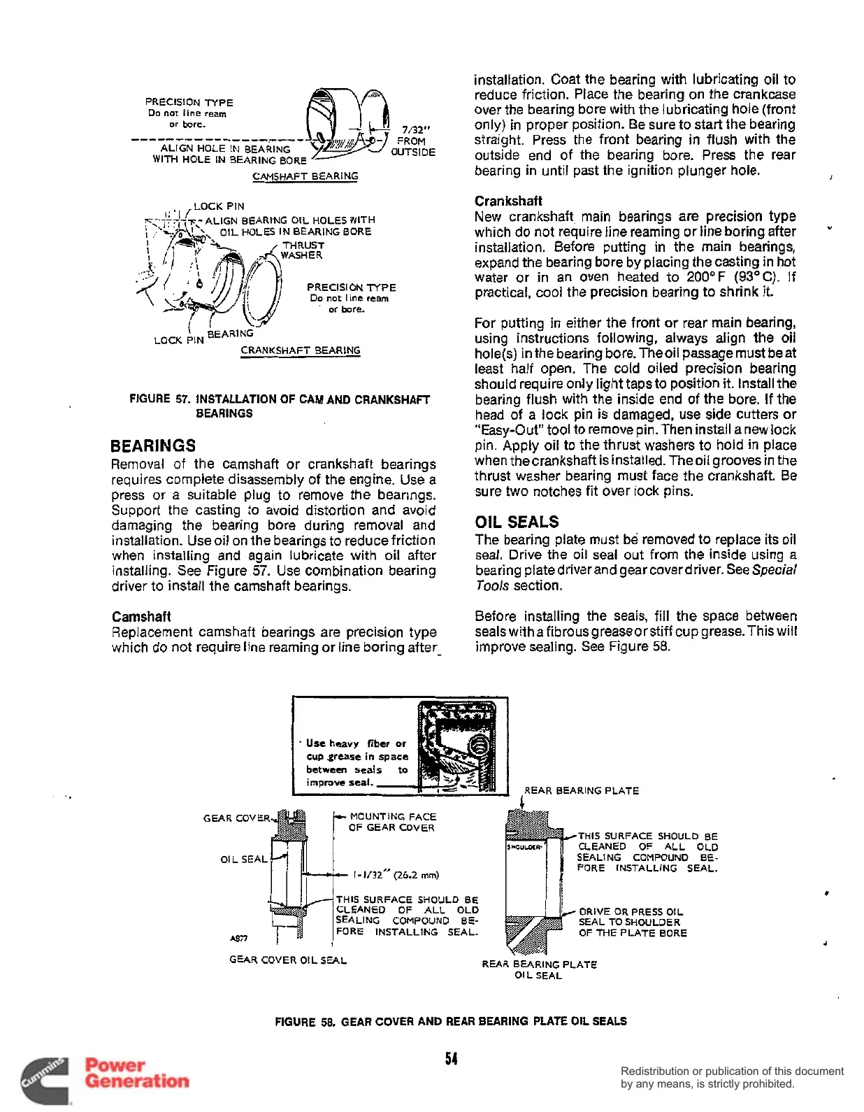
FIGURE
57.
INSTALLATION OF CAM AND CRANKSHAFT
BEARINGS
BEARINGS
Removal of the camshaft or crankshaft bearings
requires complete disassembly of the engine. Use a
press or a suitable plug to remove the bearings.
Support the casting to avoid distortion and avoid
damaging the bearing bore during removal and
installation. Use oil on the bearings to reduce friction
when installing and again lubricate with oil after
installing. See Figure
57.
Use combination bearing
driver to install the camshaft bearings.
Camshaft
Replacement camshaft bearings are precision type
which do not require line reaming or line boring after-
installation. Coat the bearing with lubricating oil to
reduce friction. Place the bearing on the crankcase
over the bearing bore with the lubricating hole (front
only) in proper position. Be sure to start the bearing
straight. Press the front bearing in flush with the
outside end of the bearing bore. Press the rear
bearing in until past the ignition plunger hole.
Crankshaft
New crankshaft, main bearings are precision type
which do not require line reaming or line boring after
installation. Before putting in the main bearings,
expand the bearing bore by placing the casting in hot
water or in an oven heated to 2OOOF
(93OC).
If
practical, cool the precision bearing to shrink it.
For putting in either the front or rear main bearing,
using instructions following, always align the oil
hole(s) in the bearing bore. Theoil passage must beat
least half open. The cold oiled precision bearing
should require only light taps to position it. Install the
bearing flush with the inside end of the bore.
If
the
head of a lock pin
is
damaged, use side cutters
or
"Easy-Out'' tool to remove pin. Then install a new lock
pin. Apply oil to the thrust washers to hold in place
when
thecrankshaftisinstalled.Theoi1groovesin
the
thrust washer bearing must face the crankshaft. Be
sure two notches fit over lock pins.
I
"
OIL
SEALS
The bearing plate must be removed to replace its oil
seal. Drive the oil seal out from the inside using a
bearing plate driver and gear cover driver. See
Special
Tools
section.
Before installing the seals, fill the space between
sealswith afibrousgreaseorstiff cup grease.Thiswil1
improve sealing. See Figure
58.
.
Use heavy fiber
or
cup .grease
in
between seal
improve seal.
MOUNTING FACE
OF GEAR COVER
GEAR COVER
OIL
SEAL^
/4
I-
1/32''
(26.2
mrn)
THIS SURFACE SHOULD BE
CLEANfD OF ALL OLD
SEALING COMPOUND BE-
FORE INSTALLING SEAL.
A877
1
REAR BEARING PLATE
THIS SURFACE SHOULD BE
CLEANED OF ALL OLD
SEALING COMPOUND BE-
FORE INSTALLING SEAL.
DRIVE
OR PRESS OIL
SEAL TO SHOULDER
OFTHEPLATEBORE
GEAR COVER O!L SEAL
REAR BEARING PLATE
OIL SEAL
FIGURE
58.
GEAR
COVER
AND REAR BEARING PLATE OIL SEALS
54
Redistribution or publication of this document
by any means, is strictly prohibited.
Redistribution or publication of this document
by any means, is strictly prohibited.
 Loading...


