Thus,
1800
rprn gives a
60
hertz frequency, and
1500
rprn gives
50
hertz frequency.
AC GENERATING SETS
Maximum No-Load Speed
RPM
Preferred speed varies approximately
3
hertz from
no-load to full-load operation. Be sure throttle, lin-
kage, and governor mechanism operate smoothly.
60
HERTZ
50
HERTZ
1890
1560
Linkage
The engine starts at wide open throttle. Length of
linkage connecting governor arm to throttle arm is
adjusted by rotating the ball joint. Adjust length
so
that with engine stopped and with tension on gover-
nor spring, the stop screw on carburetor throttle lever
is 1/32 inch from the stop pin. This setting allows
immediate control by the governor after starting, and
synchronizes travel of governor arm and throttle
shaft. See Figure 13.
*
(Without Booster)
RPM
Frequency
(Hz)
Speed Adjustment
1770
1490
59
49
1.
2.
3.
4.
5.
AC GENERATING
SETS
Maximum No-Load Volts
Minimum Full-Load
Volts
(Without Booster)
Start engine and allow to warm up without load.
WARNING
Inhalation
of
exhaust gases
n
might result in serious personal
injury
or
death. Be sure deadly exhaust gas is
piped outside and away from windows,
doors
or
other inlefs to building.
Remove vacuum booster external spring from
bracket slide on the governor link (Figure 13).
Refer to voltage and speed charts. If needed,
increase speed by increasing tension on the gov-
ernor spring. Decrease tension on the governor
spring to reduce speed.
Add a full-rated load to the engine and compare
lower speed and voltage with those shown in the
charts. If operation does not remain within these
limits, check governor linkage and governor
spring, and, if necessary, follow preceding pro-
cedure again.
Check and, if necessary, adjust governor sensitiv-
ity (see
Sensitivity
Adjustment).
120 VOLT
240
VOLT
(1
PH.
2W)
OR
OR
1201240 V
240
VOLT
(1
PH.
3
W)
(3
PH.
3W)
(1 PH .2
W)
126
252
110
,
220
Sensitivity Adjustment
1.
Start engine and allow to warm up.
2.
Check voltage and speed, first without load and
then with a full load. See voltage and speed
charts.
3.
Increasesensitivity (closer regulation) by shifting
adjusting clip toward governor shaft (Figure 13).
Move clip away from governor shaft to decrease
sensitivity.
Too
much sensitivity causes engine
to
hunt.Toolittlesensitiv-
ity
results in
too
much speed difference between no-load and
full-load conditions.
4.
A change in sensitivity adjustment usually re-
quires a compensating speed adjustment (spring
tension). Then proceed to vacuum booster ad-
justment.
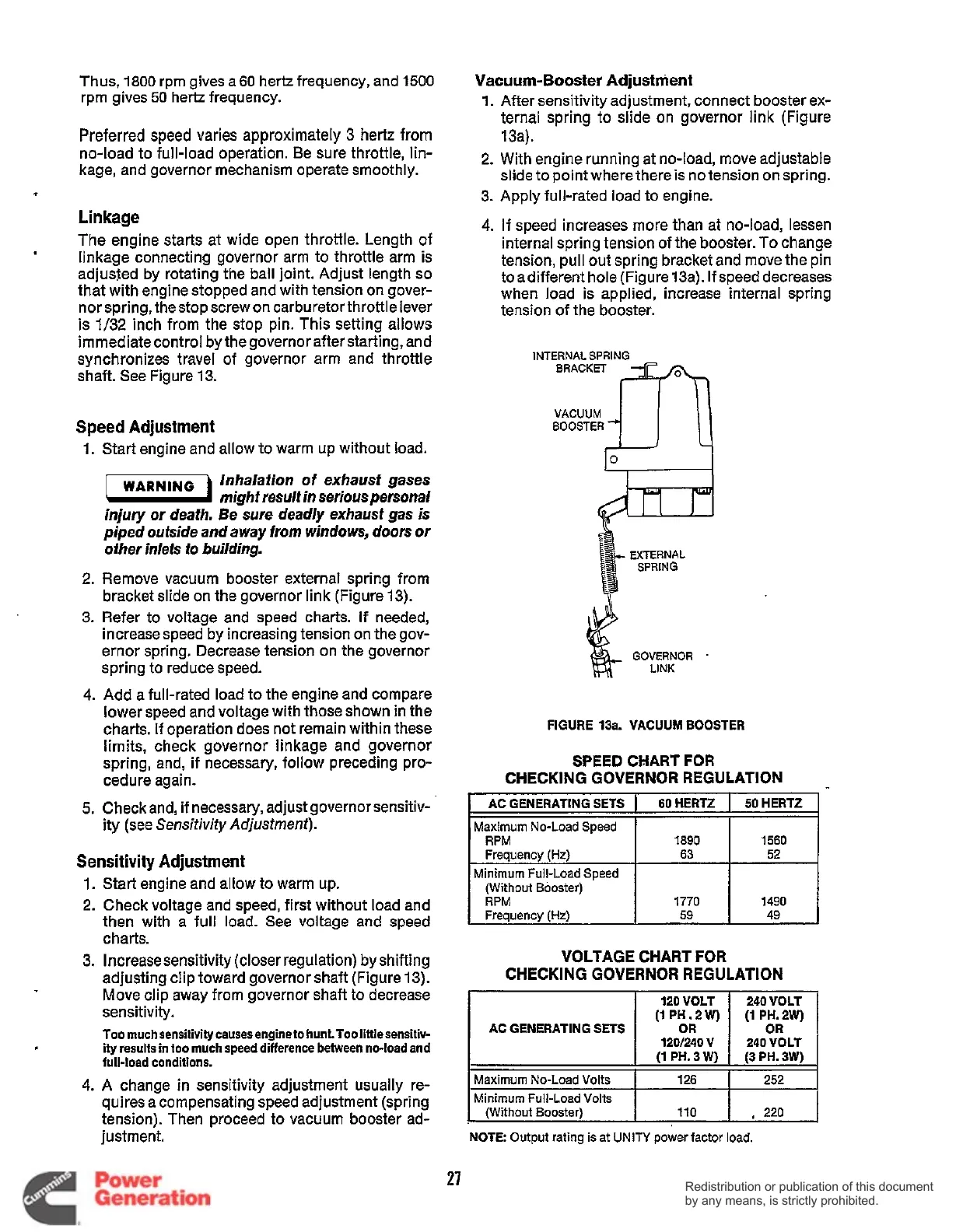
Vacuum-Booster
Adjustment
1.
After sensitivity adjustment, connect booster ex-
ternal spring to slide on governor link (Figure
13a).
2.
With engine running at no-load, move adjustable
slide to point where there
is
no tension on spring.
3. Apply full-rated load to engine.
4.
If
speed increases more than at no-load, lessen
internal spring tension of the booster. To change
tension, pull out spring bracket and move the pin
toadifferent hole (Figure 13a). If speed decreases
when load is applied, increase internal spring
tension of the booster.
VACUUM
BOOSTER
EXTERNAL
SPRING
FIGURE 13a. VACUUM BOOSTER
SPEED
CHART FOR
CHECKING GOVERNOR REGULATION
Frequency
(Hz)
I
63
I
52
Minimum Full-Load
Speed
I
VOLTAGE CHART FOR
CHECKING GOVERNOR REGULATION
27
Redistribution or publication of this document
by any means, is strictly prohibited.
Redistribution or publication of this document
by any means, is strictly prohibited.
 Loading...


